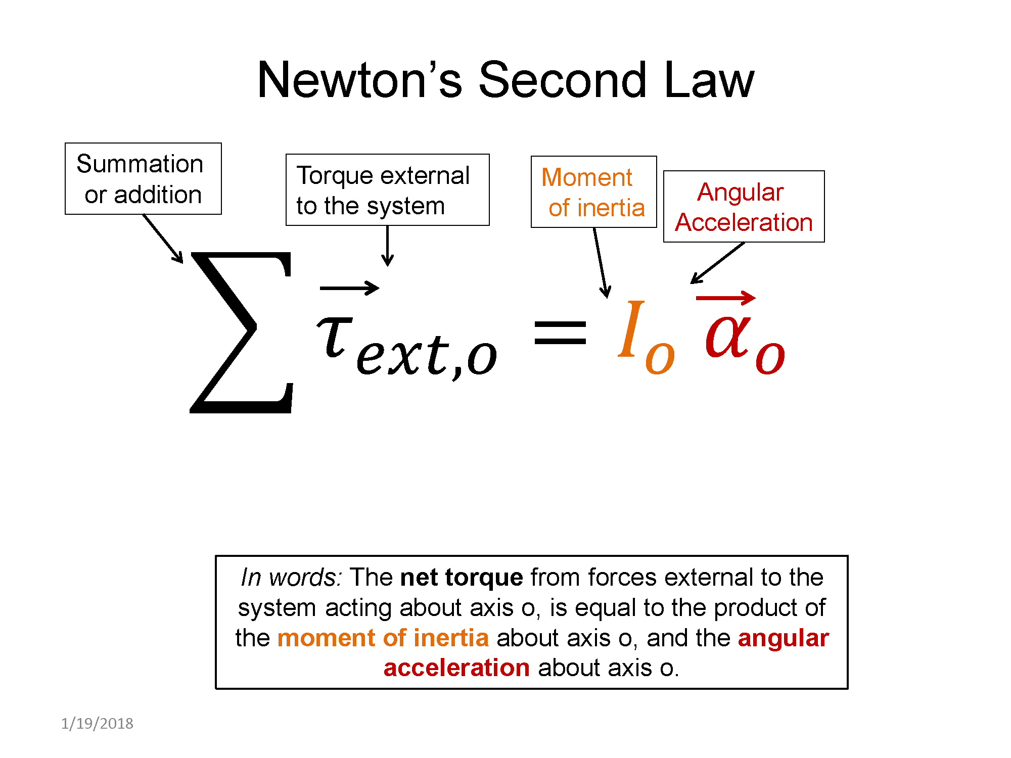
Applying Newton's 2nd law for rotation requires understanding how to calculate torques. Then you add those up and set them equal to the moment of inertia multiplied by the angular acceleration. If an object is in rotational equilibrium, the net torque must add up to zero, resulting in zero angular acceleration.
Check out this short video by OpenStax about both translational and rotational equilibrium.
https://www.youtube.com/watch?v=gfZBqviOd-M
Pre-lecture Study Resources
Watch the pre-lecture videos and read through the OpenStax text before doing the pre-lecture homework or attending class.
BoxSand Introduction
Statics & Dynamics | Application of 2nd Law: Static Equilibrium
Stability
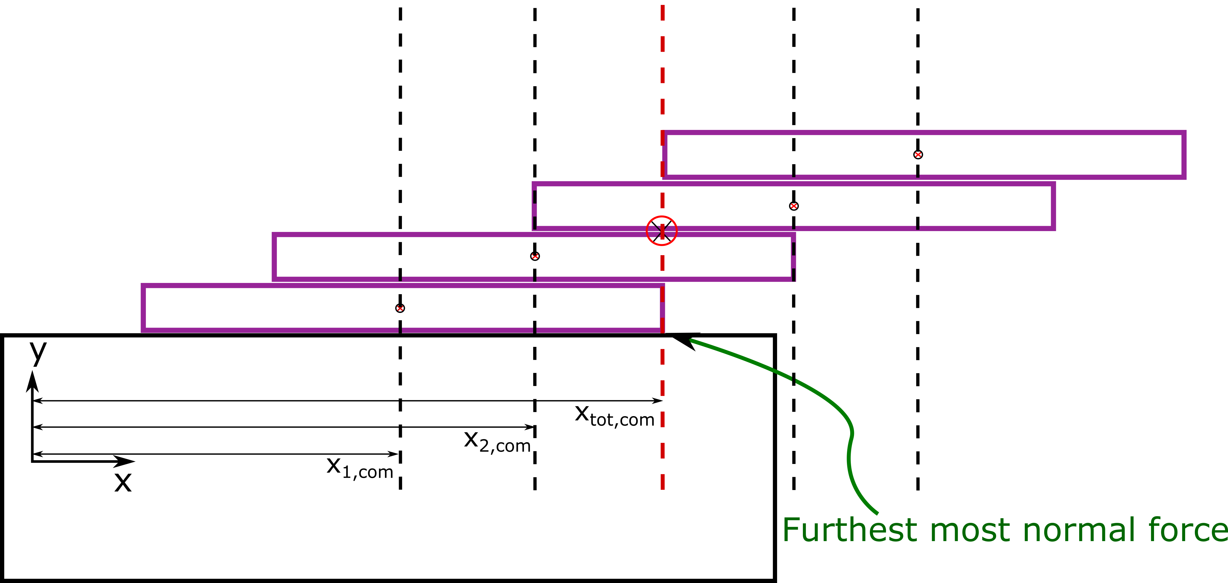
Often times summing the torque of a system of objects around an axis to determine if the system is in equilibrium or not is often tedious. It turns out we also have another method to determine the stability of a system by looking at the total center of mass of the system and its location to the furthest most normal force.
Mass is distributed within a rigid body, however, we can define a "center of mass" (com) location for an object or system of objects. This is useful because if our object is in a uniform gravitational field (much like the approximate uniform gravitation field near the surface of the Earth), then the force of gravity that acts over the entire body of the object can be simplified and treated as if it acts through only the center of mass of the object. The center of mass will have a x, y, and z-component, but often times we can just consider the x and y-component because the z-component is of no importance to our problem. Mathematically we find the center of mass of a system of objects as follows:
$x^{tot}_{com} = \frac{x^{1}_{com}m_1 +x^{2}_{com} m_2 +x^{3}_{com} m_3 +...}{m_1 + m_2 + m_3 + ...} = \frac{\sum{x^{i}_{com} \, m_i}}{\sum{m_i}}$
$y^{tot}_{com} = \frac{y^{1}_{com}m_1 +y^{2}_{com} m_2 +y^{3}_{com} m_3 +...}{m_1 + m_2 + m_3 + ...} = \frac{\sum{y^{i}_{com} \, m_i}}{\sum{m_i}}$
As an example, the figure below shows a system of 4 objects with each of their individual center of masses identified by the small circle with the dotted block line going through it. The condition as shown below is the case where the system will not tip over, but if the center of mass shifted just slightly to the right, then it would tip.
Key Equations and Infographics

Now, take a look at the pre-lecture reading and videos below.
BoxSand Videos
Required Videos
Suggested Supplemental Videos
OpenStax Reading
OpenStax Section 9.3 | Stability
OpenStax Section 9.4 | Applications of Statics, Including Problem-Solving Strategies
OpenStax Section 9.5 | Simple Machines
OpenStax Section 9.6 | Forces and Torques in Muscles and Joints
Fundamental examples
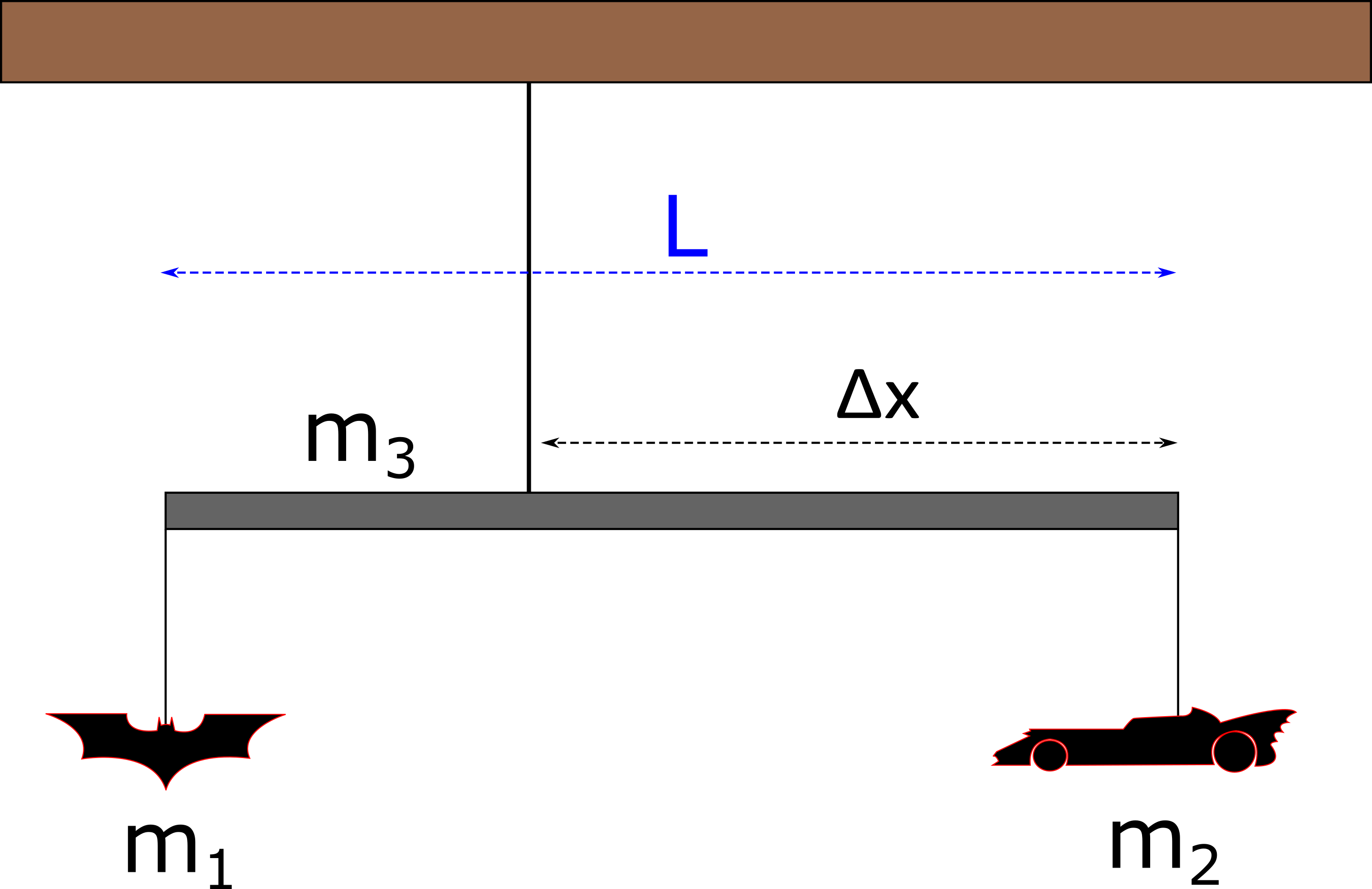
1. A very simple mobile that hangs from a ceiling can be constructed with a rigid rod of uniform density and length $L$, that has two plastic toys hung from the rod's ends as seen in the figure below. At what distance from the right side of the rod must you connect the string that attaches to the ceiling such that the system is in static equilibrium? Let $m_1 = 0.5 \, kg$ and $m_2 = 1.5 kg$.
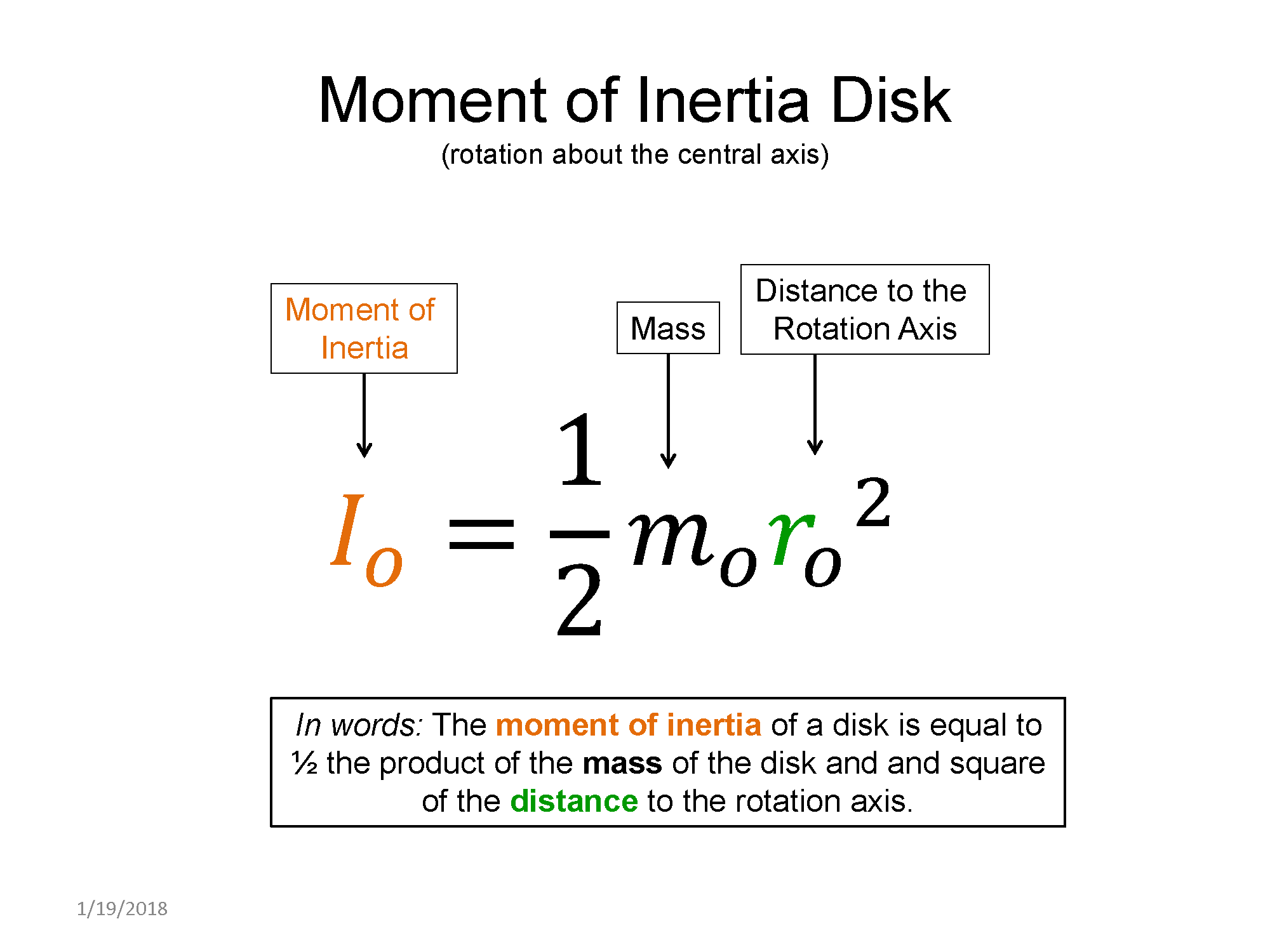
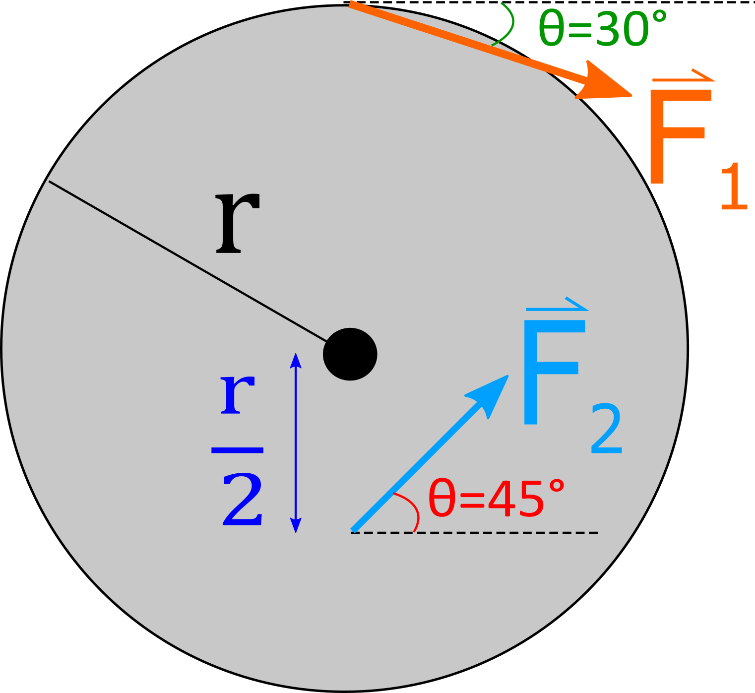
2. The figure below shows two forces acting on a $7 \, kg$ solid disk that is free to rotate about it's center and has a diameter of $d = 3 \, m$. What must the magnitude of $\vec{F}_2$ be such that the disk is in static equilibrium? The moment of inertia for a solid disk about it's center, perpendicular to the face of the disk, is $\frac{1}{2} m \, r^2$, where $r$ is the radius. Let $| \vec{F}_1|=10 \, N$.
3. During the initial stages of building a Death Star, Tiaan Jerjerrod attached two very small rockets to a large quadanium steel beam with uniform density, located in deep space, as seen in the figure below. Both rockets provide a constant thrust of $500 \, N$. Tiaan wishes to rotate the beam by 90 degrees. The length of the beam is $L=60 \, m$. The beam's mass is $6.4 \times 10^{4} \, kg$, and the moment of inertia about the center of the beam is $\frac{1}{12} m \, L^2$.
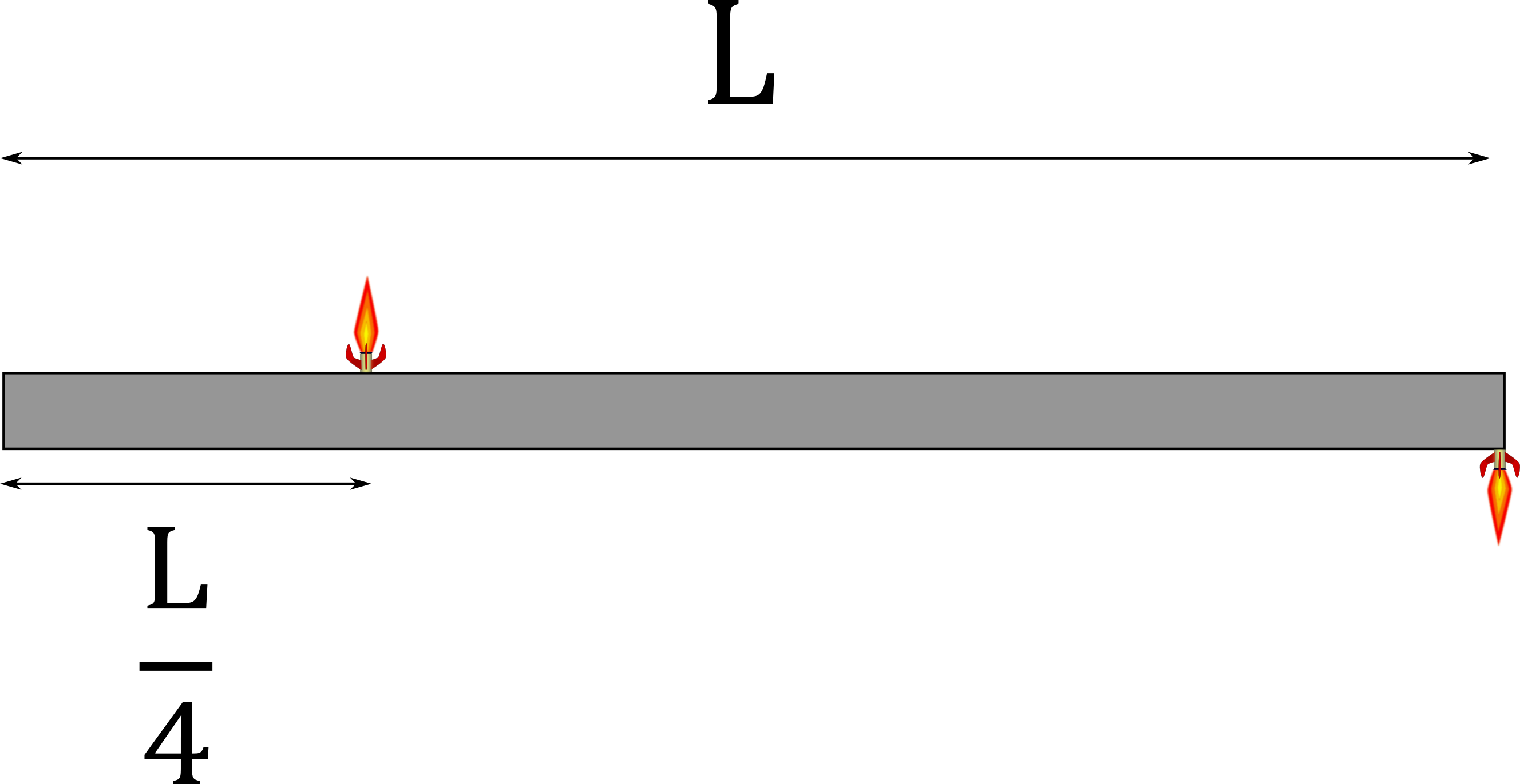
(a) What is the angular acceleration of the beam?
(b) How long does it take to rotate the beam by $90^{\circ}$?
(extra) ... Just before the $90^{\circ}$ mark, do you need to turn off the thrusters to stop the rotation?
CLICK HERE for solutions.
Short foundation building questions, often used as clicker questions, can be found in the clicker questions repository for this subject.
Post-Lecture Study Resources
Use the supplemental resources below to support your post-lecture study.
Practice Problems
Recommended example practice problems
- set 1: Problems with solutions, Website Link
- set 2: Static net torque = 0, Website Link
- set 3: PDF of free body diagram problems, Offsite PDF Link
For additional practice problems and worked examples, visit the link below. If you've found example problems that you've used please help us out and submit them to the student contributed content section.
Additional Boxsand Study Resources
Additional BoxSand Study Resources
Learning Objectives
Summary
The objective is to analyze forces acting to cause or prevent rotation of a rigid body using the concepts of torque, which is an application of the cross-product, and Newton's 2nd Law for Rotation. Special emphasis is placed on connecting a net torque to a net force analysis, including concepts of center of mass and moment of inertia.
Atomistic Goals
Students will be able to...
- Identify and define the cross product as a vector operation and show that it increases as the vectors become more perpendicular.
- Differentiate between a dot product and a cross product.
- Define the magnitude of a cross product as the magnitude of the first vector times the magnitude of the second vector, times the sin of the smallest angle between the two, when placed tail to tail.
- Differentiate a reference axis from a coordinate system and an origin.
- Identify that a torque is a cross product between a position vector that points from the reference axis to the point where a force is applied and that applied force.
- (UPMF) Explain that a torque is a vector, yet we limit our study to forces in a plane, allowing the vector nature to be accounted for with a sign convention.
- Find the sign of the component of torque by determining if the force would make the object rotate clock-wise (cw) or counter clock-wise (ccw), with convention being that ccw is positive and cw is negative.
- (UPMF) Differentiate a point-particle and rigid body analysis.
- Explain Newton's 2nd law for both point particles and rigid bodies and compare and contrast the two.
- Identify the axis a system would rotate about if allowed to evolve.
- Choose a reference axis that simplifies the mathematical representation of Newton's 2nd Law for Rotation.
- Draw an extended free-body diagram (eFBD) which includes a representation of the shape of the rigid body, the force vectors where they act on the body, and position vectors pointing from the reference axis to the force locations.
- Draw a vector operational physical representation for every force and its associated position vector by placing them tail-to-tail.
- Use the vector operation diagram for a cross product to determine (1) what the smallest angle between the force and position vector is and (2) whether the torque is relatively large or small.
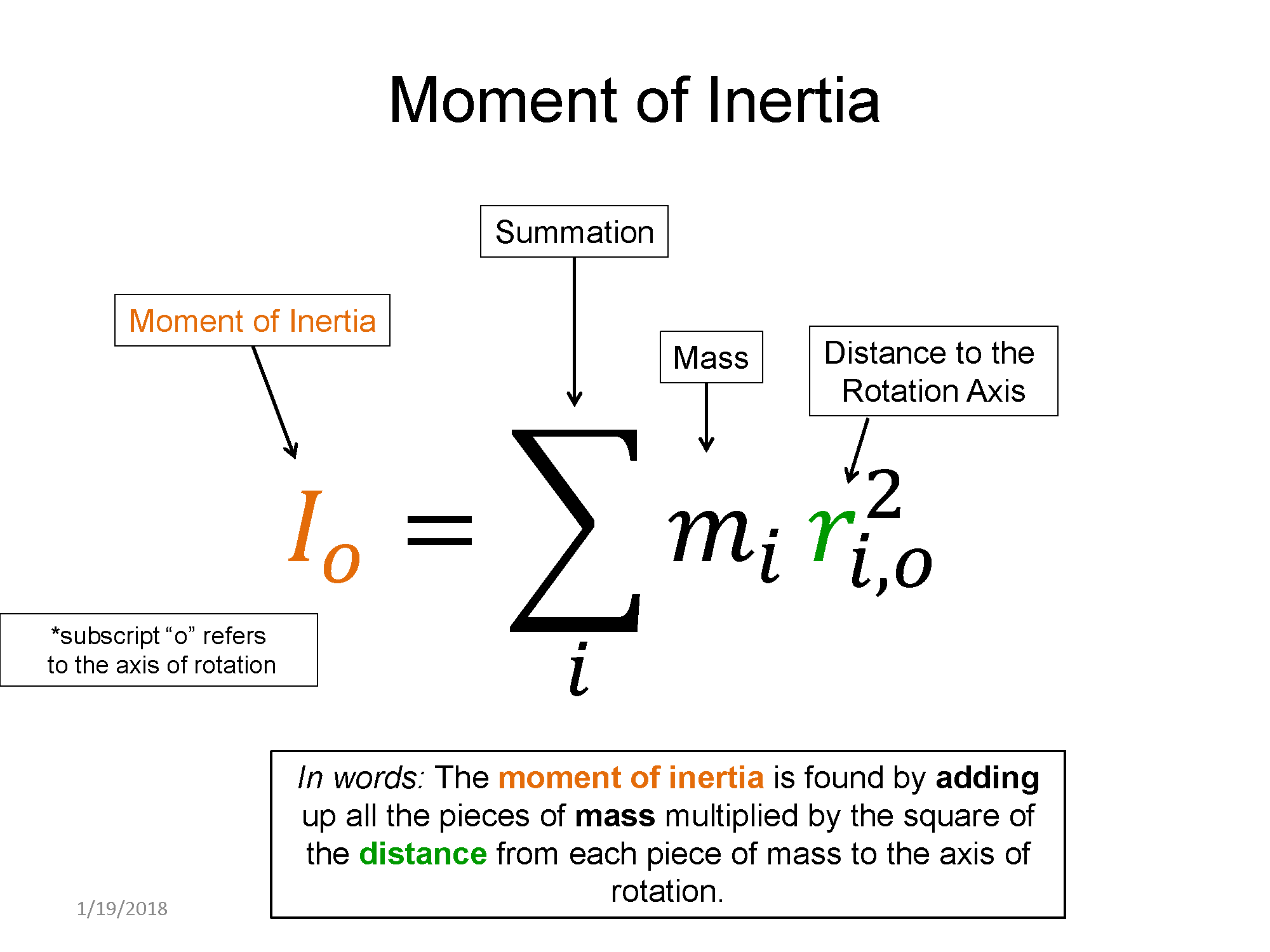
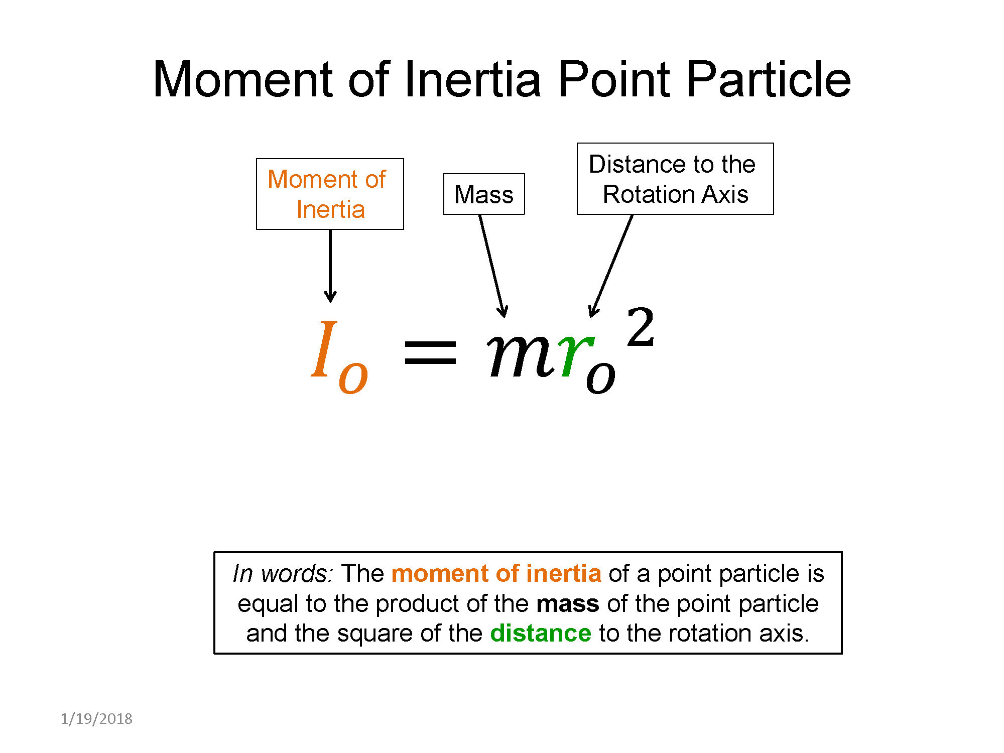
- Define the moment of inertia and determine its magnitude based on the distribution of mass relative to the reference axis.
- Add multiple moments of inertia to determine the net moment of inertia for multiple objects about a reference axis.
- Differentiate between static and dynamic equilibrium for both rotational and translational mechanics.
- Apply Newton's 2nd Law for Rotation of rigid static bodies.
- Apply Newton's 2nd Law for Rotation of rigid dynamic bodies.
- Connect rotational kinematics and mechanics via the angular acceleration.
- Simultaneously apply a translational and rotational Newton's 2nd Law analysis to a system.
- Analyze a system including a frictionless massive pulley.
- Estimate the center of mass for an object or a system of multiple objects.
- Calculate the center of mass for a system of multiple objects where their individual center of mass is known.
- Demonstrate that an unconstrained system rotates about its center of mass.
- (UPMF) Show that for an unconstrained object under the influence of gravity, the object will tip over if the center of mass is horizontally beyond the outermost vertical normal force.
YouTube Videos
Crash Course Physics does a great job of introducing torque with everday examples.
https://www.youtube.com/watch?v=b-HZ1SZPaQw
Pre-Med Academy introduces torque.
https://www.youtube.com/watch?v=fFybBrziXgI
Bozeman Science covers statics.
https://www.youtube.com/watch?v=/5Zrphnd_0VI?list=PLllVwaZQkS2ovAYcBy_kwB534xHgXmvHY
Khan Academy explains how to find torque for anlged forces.
https://www.youtube.com/watch?v=ZQnGh-t25tI
Moment of inertia explanation. At 12:25 doc begins to derive moments of inertia for various objects, you can ignore this.
https://www.youtube.com/watch?v=PBo7llsc6LA
Doc Schuster talks about rotational dynamics.
Simulations
PhET simulation on dynamic torque. Note that when you let the wheel rotate without acceleration, it is actually in torsional equilibrium despite the fact that it is in motion.
For additional simulations on this subject, visit the simulations repository.
You need to have Java installed and updated. Download and run the file.
Demos
Toothpick "breaks" physics... or does it?
https://www.youtube.com/watch?v=A18vUTsw1zA
For additional demos involving this subject, visit the demo repository
History
Oh no, we haven't been able to write up a history overview for this topic. If you'd like to contribute, contact the director of BoxSand, KC Walsh (walshke@oregonstate.edu).
Physics Fun
Proper lifting technique to minimize the torque on your back by minimizing the moment arm.
https://media.oregonstate.edu/media/t/0_rrr2h2ii
Check out a tower of lire and how it relates to statics
Other Resources
Read pages 1-10 for static equilibrium.
This links to a set of slides detailing static equilibrium.
Other Resources
This link will take you to the repository of other content related resources.
Resource Repository
This link will take you to the repository of other content related resources.
Problem Solving Guide
Use the Tips and Tricks below to support your post-lecture study.
Assumptions
- 1. Static equalibrium means the sum of all forces AND the sum of all torques is equal to 0. This means most powerful analysis techniques for these problems will be summing forces and torques.
- 2. After drawing an extended free body diagram (eFBD), the next best step is usually to sum forces for the system in the x and y direction (acceleration is 0, so unless you just want to do less work, summing along the x and y should always work!). Then, sum your torques.
- 3. Summing torques has a bit of conceptual difficultly to it in that you need to chose a spot to sum around. Because torque is force times distance times the sine of the angle, if you find the torque at a point where the force is applied, that force disappears from the calculaton because the distance in our calculation (distance of the moment arm) is 0! This is usually extremely convienent or necessary to solving problems in this section. With this in mind, chose carefully where you sum torques around, you usually don't want to sum around the force you want to find, however, if there are one or more forces you don't know and don't care about, summing torques around where those forces are applied is usually a great move since all the forces you don't know there will be multiplied by 0 distance and thus drop out of your calculation!
Checklist
- Read and re-read the whole problem carefully.
- Visualize the scenario. Mentally try to understand what the rigid body is doing and what forces are acting on it along with the location of the forces on the body.
- Draw a physical representation of the scenario, this may include a FBD and/or an e-FBD.
- Draw all forces acting on the object at the known locations. (Helpful hint: Draw a FBD first. All the forces on the FBD will show up on the e-FBD, no more, no less.)
- Define a coordinate system on your e-FBD. Conventional coordinate system is ccw(+) and cw(-).
- Label a location that represents the axis that you would sum torques around. The location of this axis can be placed anywhere, but defining it to be at the location of unknown forces is a good way to eliminate the torque due to the unknown force.
- Specify the moment arms for all forces acting on the e-FBD.
- Identify all the known and unknown terms.
- Use Newton's rotational version of the second law and sum the torques around the axis you chose.
- Identify if the object is in rotational equilibrium or not to determine the value of the angular acceleration.
- If the angular acceleration is not zero, determine the moment of inertia of the object around the axis you chose.
- Determine the number of unknowns from your rotational version of Newton's second law equation. If more than 1, perhaps choose a different axis to sum the torques around, or draw a regular FBD to build more equations.
- Carry out the algebraic process of solving the equation(s).
- Evaluate your answer, make sure the units are correct and the results are within reason.
Misconceptions & Mistakes
- The axis you choose to sum the torques around does not have to be the actual pivot point that the object would rotate around.
- When calculating torque, do not forget to add a positive or negative based off of the direction that the force wants to rotate the rigid body about the axis you chose.
- An object does not have a single moment of inertia. The moment of inertia depends on the axis that the object would rotate around. Thus objects can have many moments of inertia for different axes.
- Torque has the same dimensions of energy, but torque is not a form of energy. Torque is a vector, and energy is a scalar
Pro Tips
- For any force that is not parallel or perpendicular to the moment arm, take the time to draw a vector operation to determine the correct angle between the force and moment arm.
- If you are having troubles identifying forces for an e-FBD, draw a regular FBD first. The same forces that show up on a regular FBD for an object show up on an e-FBD for the same object. In addition, often-times using both a translation analysis and a rotational analysis together will help expedite the process of solving the problem.
- Identify all the known and unknown forces on your e-FBD before you define an axis to sum the torques around. Once you know which forces are unknowns, try defining your axis through the location of the unknown forces to eliminate the unknown force in the final equation derived from summing the torques.
- If there is a torque which an unknown direction, just guess the direction and apply the rotational analysis of summing the torques. For example, if you guess a torque to be ccw(+), and you get a negative number for the value of that torque, then you define the direction incorrectly initially, if the value was positive, then you guess correctly (assuming no algebraic mistakes).
- Scaling forces and distance on an e-FBD can help you visualize the contribution of each torque from each force. When finished solving the problem, you can then go back to your scaled drawling to see if the answer is what you were expecting.
Multiple Representations
Multiple Representations is the concept that a physical phenomena can be expressed in different ways.
Physical
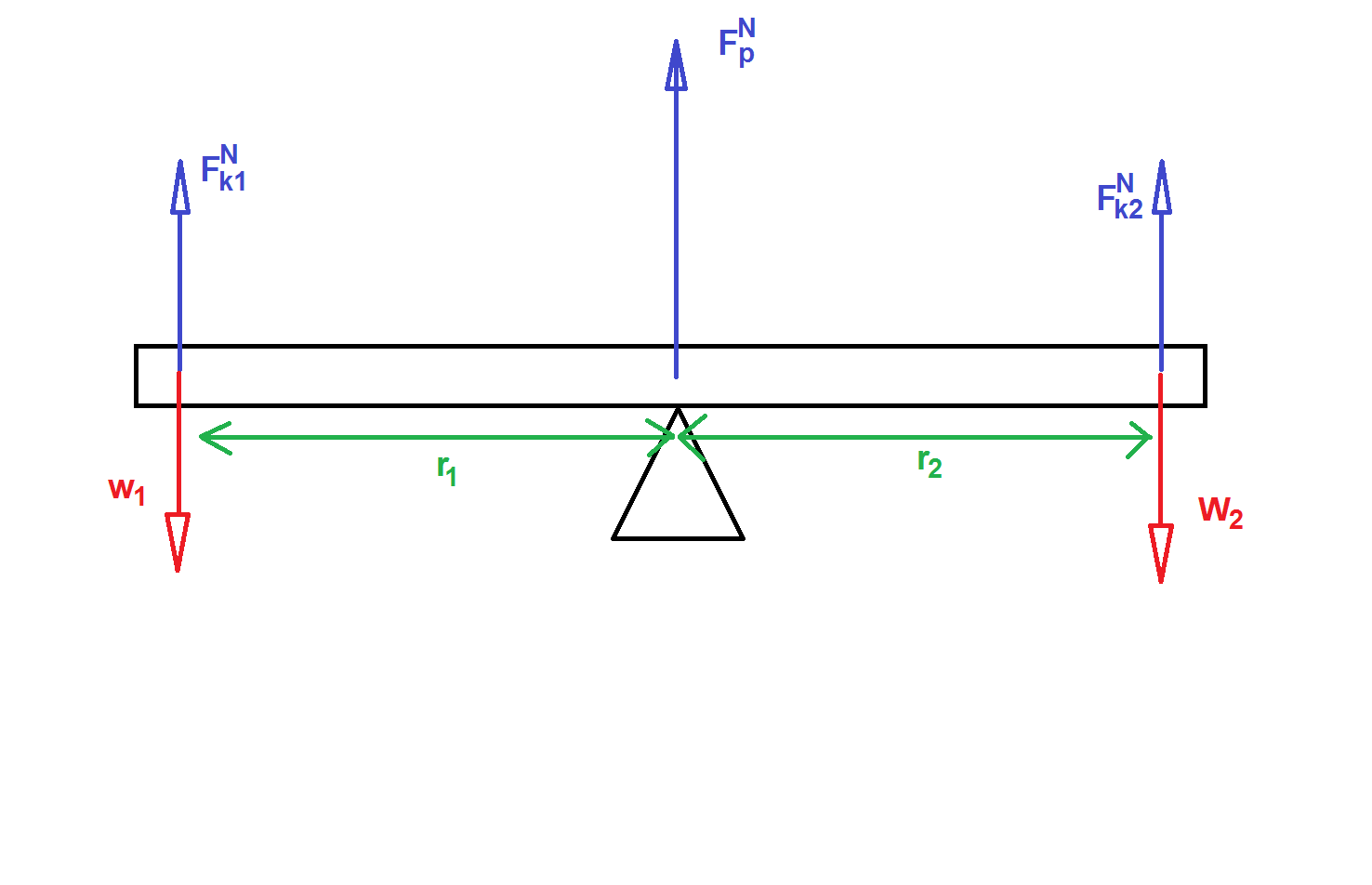
We represent the system with an extended free body diagram which places the forces at locations, lets consider two kids on a seesaw.

Naturally your not expected to draw something as complex as the above, you should draw something like the following.
Mathematical
Forces acting on an object can cause torque about some given axis. Torque ($\tau$) is defined as a cross product between force and displacement.
$\tau = r \times F$, r is the displacement vector from the axis of interest to the location the force is applied.
Remember to take geometry into account when calculating torque! Only the force component perpendicular to $r$ contributes to the torque.
$|\tau| = |r| |F| \sin \theta$
With regards to our seesaw scenario, the net torque of the see saw about its pivot axis is,
$\sum \tau = r_1 \times F^{N}_1+r_2 \times F^{N}_2$
If $\tau_{net} = 0$, then we say that the system is in rotational equilibrium.
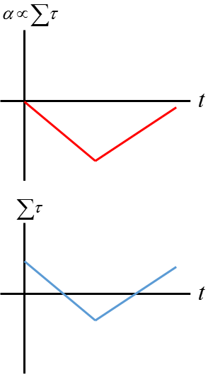
The net torque and moment of inertia about a chosen axis tells us something about the angular acceleration of that body about that same axis.
$\alpha = \frac{\sum \tau}{I}$


Graphical
Rotational acceleration is proportional to the net sum of all the torque.
Descriptive
Two children sit on a seesaw. Child 1 sits a distance of $r_1$ from the pivot. On the other side, child 2 sits a distance of $r_2$ from the pivot.
Experimental
Find a straight long flat piece of wood like the one in the figure below. Next, grab some objects to place on the piece of wood. Now, place the piece of wood on top of a fulcrum and add arrange some objects on it so that the piece of wood balances on the fulcrum. You can vary the position of the wood and try placing the objects in a new arrangement to see where they need to go in order to find the equilibrium.
