Check out this short animation of simplifying a circuit.
Pre-lecture Study Resources
Watch the pre-lecture videos and read through the OpenStax text before doing the pre-lecture homework or attending class.
BoxSand Introduction
Subject | Lecture
We have previously learned how to analyze circuits using Kirchhoff's laws and Ohm's law. The method is by far the most general and will always work when trying to analyze a circuit. However, there are many different methods of analyzing circuits. In this section we will look at one such alternative method.
Some circuits have their elements connected in such a way that it is easily possible to reduce the circuit into a representative circuit consisting of only a battery and a resistor connected to each other. The ability to reduce a complicated circuit into a simpler one is often an easier way to analyze the circuit. In order to reduce a complex circuit into a simpler one, we need to first identify the two simplest ways of connecting elements and how each way can be reduced. Two of the easiest resistor combinations to reduce are known as series and parallel.
Resistors in series
When two or more elements are connected in such a way that no junctions are connected between them, then we refer to this arrangement as a series connection. The elements can be resistors, capacitors, inductors, lightbulbs etc. In this section we will only look at how resistors (and ideal lightbulbs) in series can be simplified.
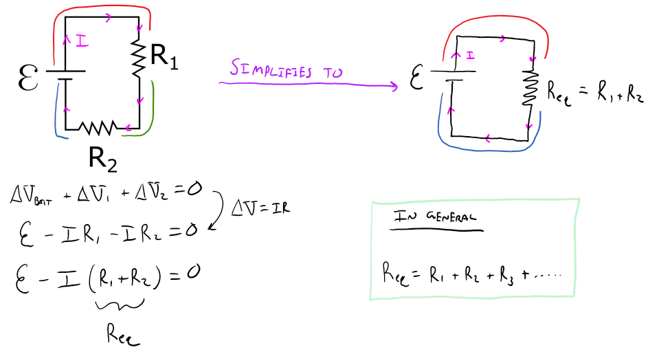
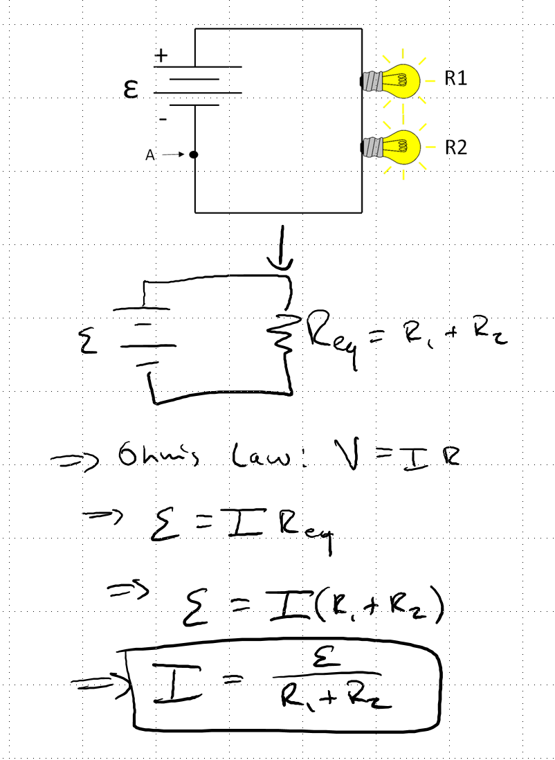
Below is a circuit diagram with two resistors in series. Using Kirchhoff's law's and Ohm's law we can create an equation, from which emerges a pattern for resistors in series. The pattern is: resistors in series can be replaced by a single resister of equivalent resistance equal to the sum of the individual resistance of each resistor that is in the series arrangement.
Note that as you add more resistors in parallel the total resistance increases, and with Ohm's law, this means that the current decreases.
Resistors in parallel
When two or more elements are connected in such a way that the change in voltage across each element is the same, then we refer to this arrangement as a parallel connection. The elements can be resistors, capacitors, inductors, lightbulbs etc. In this section we will only look at how resistors (and ideal lightbulbs) in parallel can be simplified.
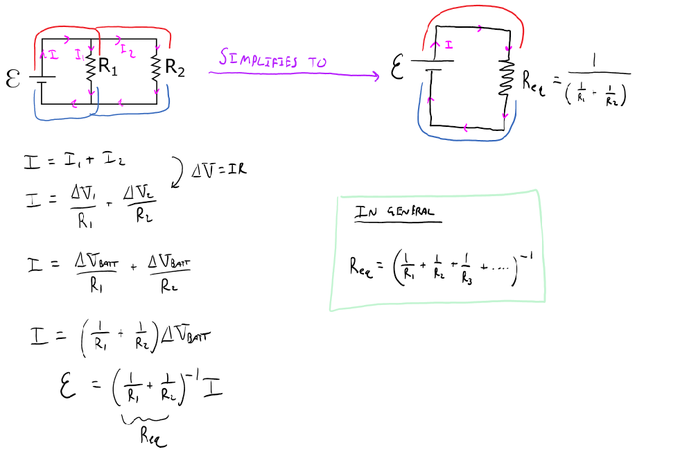
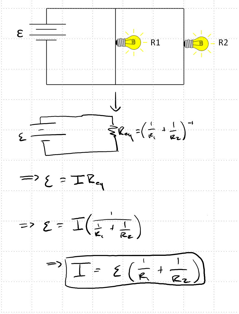
Below is a circuit diagram with two resistors in parallel. Using Kirchhoff's law's and Ohm's law we can create an equation, from which emerges a pattern for resistors in parallel. The pattern is: resistors in parallel can be replaced by a single resister of equivalent resistance equal to one over the sum of the inverse of the individual resistance of each resistor that in in the parallel arrangement.
Note that as you add more resistors in parallel the total resistance decreases, and with Ohm's law, this means that the current increases.
The general idea for analyzing circuits with a series and/or parallel resistors is to reduce the circut to the most basic form of just one battery and one equivalent resistance. Along the way you might have to do multiple steps, for example, you may need to reduce a few reisitors in series first, then reduce more resisitors in parallel until you reach one equivalent resistance. The trick is to always draw the reduced circuit at each step. Once you reach the most reduced form of the circuit, use a combination of Ohm's law and Kirchhoff's laws as you work your way backwards through each previous reduced circuit.
Key Equations and Infographics


Now, take a look at the pre-lecture reading and videos below.
BoxSand Videos
Required Videos
Suggested Supplemental Videos
OpenStax Reading
OpenStax Section #.# | Title -- From Fundamentals
Openstax's section on Resistors in series and parallel.
![]()
Fundamental examples
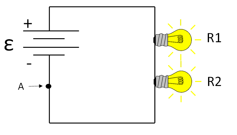
(1) Consider the simple circuit diagram below. In terms of the variables given on the diagram, what is the current at point A?
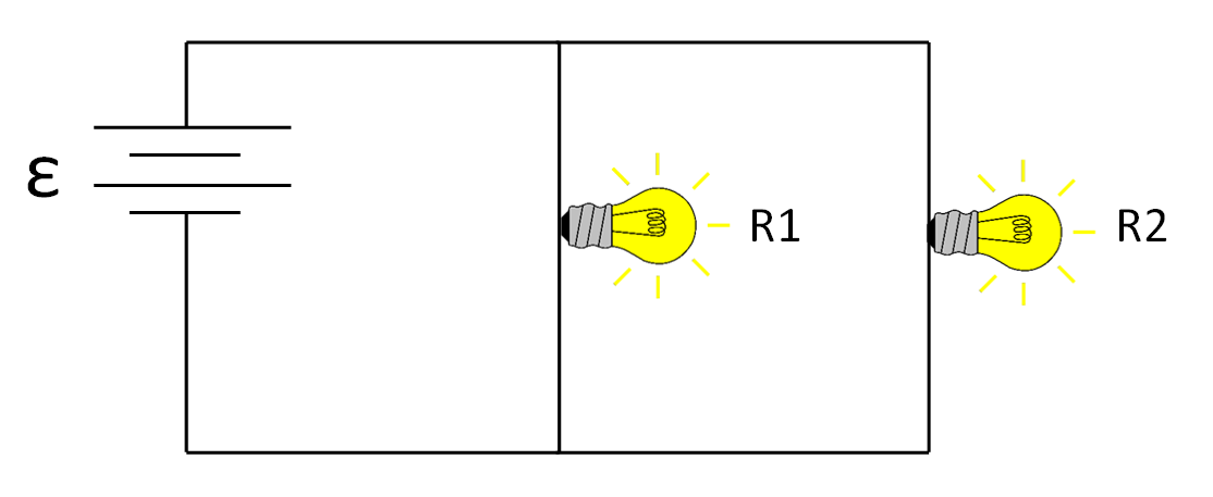
(2) Consider the simple circuit diagram below. In terms of the variables given in the diagram, what is the current flowing through the battery?
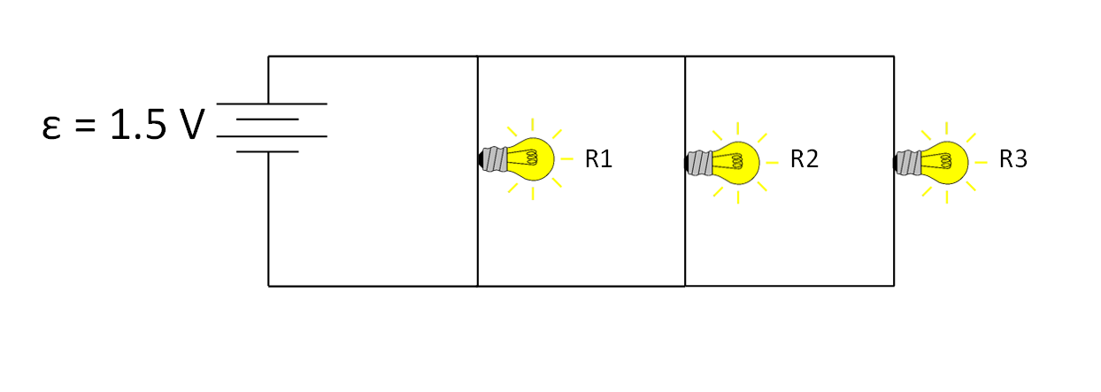
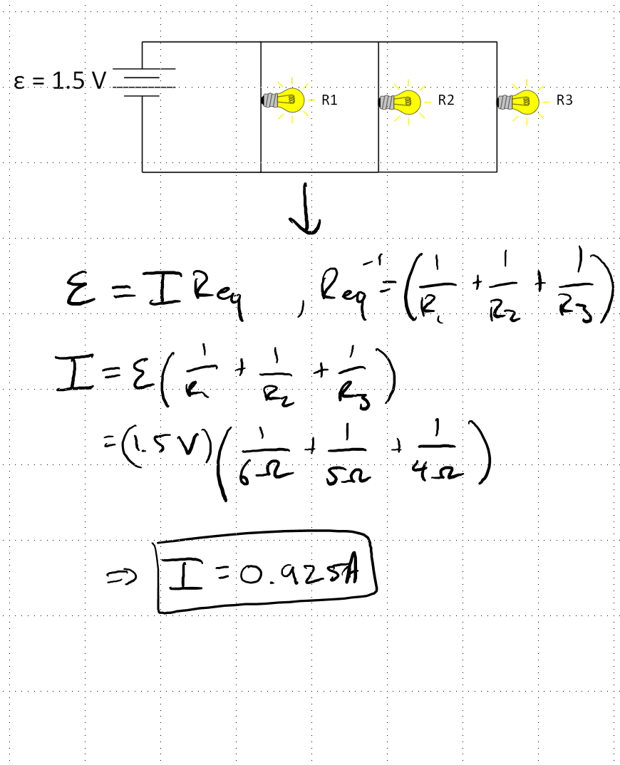
(3) Consider the same circuit as before but with one additional resistor. If $R_1 = 6 Ω$, $R_2 = 4 Ω$, and $R_3 = 5 Ω$, what is the new current flowing through the battery?
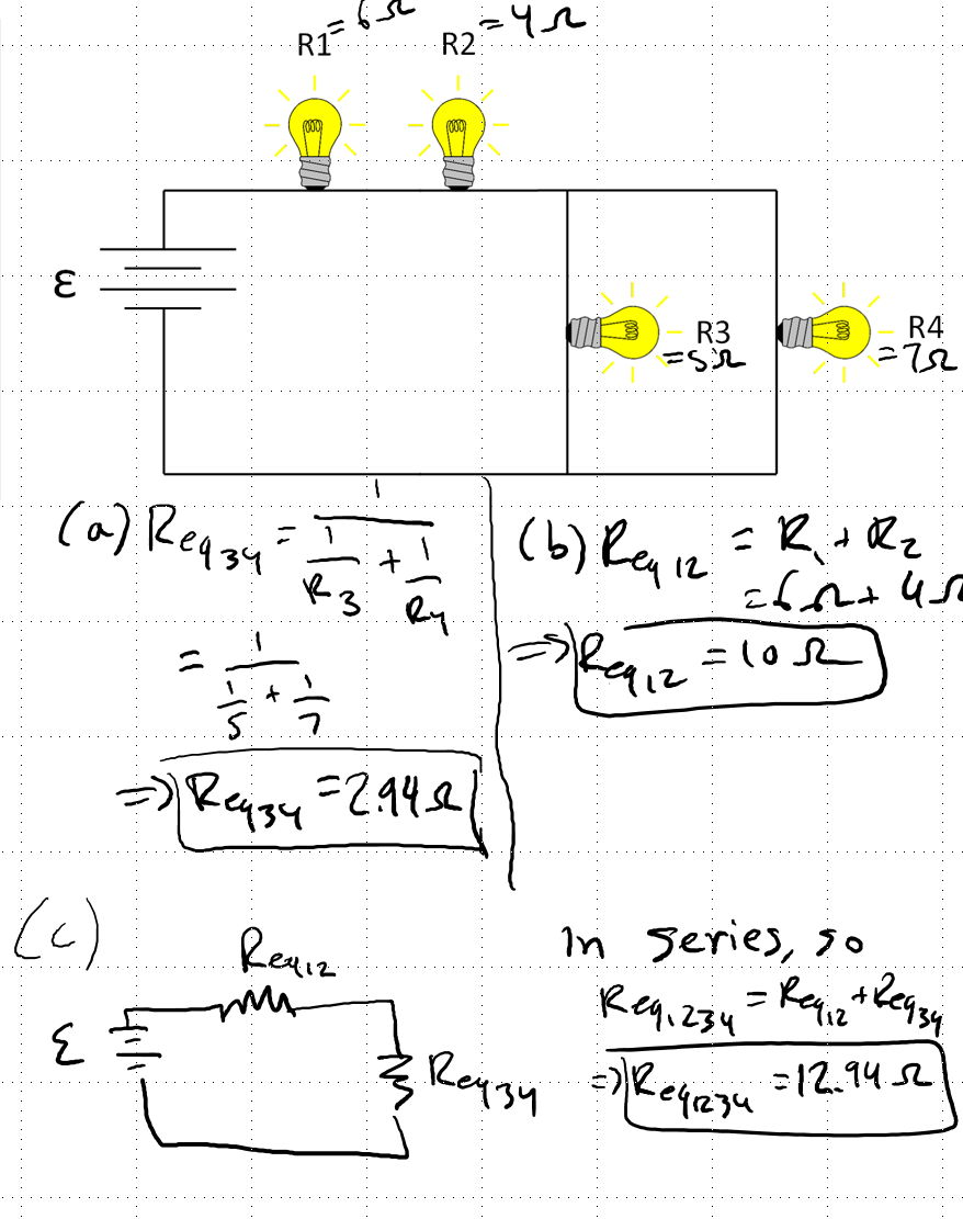
(4) Consider the circuit below. The values of the resistors are $R_1 = 6 Ω$, $R_2 = 4 Ω$, $R_3 = 5 Ω$, and $R_4 = 7 Ω$, and $ε = 1.5 V$.
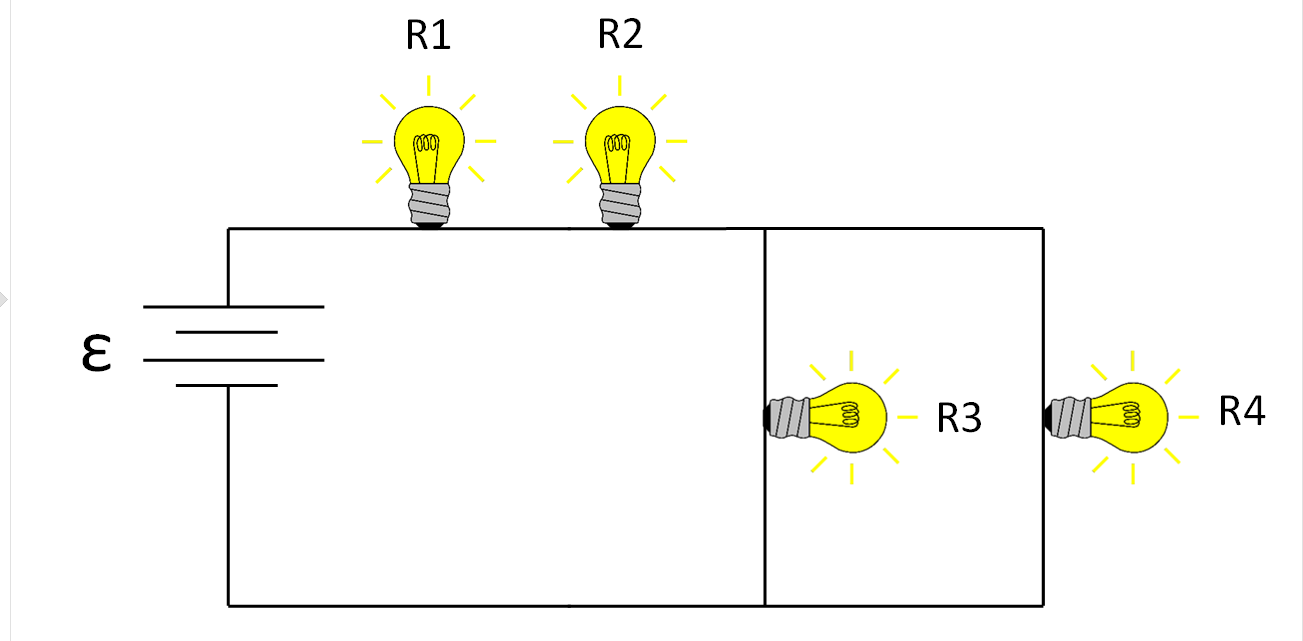
(a) What is the equivalent resistance of $R_3$ and $R_4$: $R_{eq34}$?
(b) What is the equivalent resistance of $R_1$ and $R_2$, $R_{eq12}$?
(c) What is the equivalent resistance of the circuit, $R_{eq1234}$?
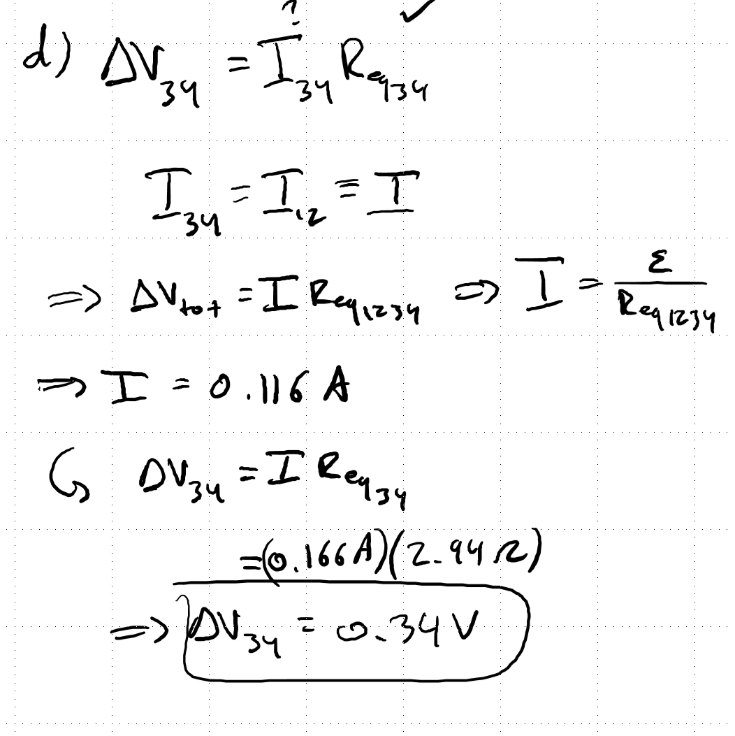
(d) What is the $\Delta V_{34}$?
While we continue to work on making custom content check out these two guided exercises from the University of Wisconsen-Green Bay.
- University of Wisconsin-Green Bay
- Electric Current II (Mathematical), Website Link
- Electric Circuit II (Conceptual), Website Link
Short foundation building questions, often used as clicker questions, can be found in the clicker questions repository for this subject.
![]()
Post-Lecture Study Resources
Use the supplemental resources below to support your post-lecture study.
Practice Problems
BoxSand's quantitative practice problems
Recommended example practice problems
- OpenStax, problems at bottom of page,**
- Resistors in Series and Parallel, Website Link
- Physics Hypertextbook, Resistors in Circuits, Website Link
For additional practice problems and worked examples, visit the link below. If you've found example problems that you've used please help us out and submit them to the student contributed content section.
Additional Boxsand Study Resources
Additional BoxSand Study Resources
Learning Objectives
Summary
Summary
Atomistic Goals
Students will be able to...
YouTube Videos
Doc Schuster covers Equivalent resistances of resistors and how to analyze parallel and series resistor circuits.
https://www.youtube.com/watch?v=CZgqGTxL9cA
Pre-Med Academy's series on the electric current covers Resistors in parallel and in series.
https://www.youtube.com/watch?v=CyyUhPNOjTA
Here are a couple of videos from Step-by-Step Science where they calculate voltage resistance and current for resistors in series, then in parallel.
Other Resources
This link will take you to the repository of other content related resources .
![]()
Simulations
This PhET is their Circuit Construction Kit. See if you can use what you know abour resistors in parallel in series to make predictions on how the circuit will behave.
![]()
For additional simulations on this subject, visit the simulations repository.
![]()
Demos
For additional demos involving this subject, visit the demo repository
![]()
History
Oh no, we haven't been able to write up a history overview for this topic. If you'd like to contribute, contact the director of BoxSand, KC Walsh (walshke@oregonstate.edu).
Physics Fun
Other Resources
Resource Repository
Boston University's page on series and aprallel resistance
![]()
PPLATO is a complete resource with a lot of information, and several practice questions per subject. This webpage coveres electric current and Circuits, which includes resistors in series and parallel. Use the sidebar of the website for quicker navigation.
![]()
Other Resources
This link will take you to the repository of other content related resources .
![]()
The Physics Classroom has a section on Series, Parallel, and Combination Circuits.
| Series Circuits | Parallel Circuits | Combination Circuits |
Problem Solving Guide
Use the Tips and Tricks below to support your post-lecture study.
Assumptions
Checklist
Misconceptions & Mistakes
Pro Tips
Multiple Representations
Multiple Representations is the concept that a physical phenomena can be expressed in different ways.
Physical
Mathematical
Graphical
Descriptive
Experimental