When light shines on a very thin film, interference can occur. Sometimes the interference pattern can be quite striking, as in the case of an oil slick.

Here is a cool video displaying thin film interference in action.

https://www.youtube.com/watch?v=4I34jA1fDp4

Pre-lecture Study Resources

Watch the pre-lecture videos and read through the OpenStax text before doing the pre-lecture homework or attending class.

BoxSand Videos

Learning Objectives

Summary

Summary

Atomistic Goals

Students will be able to...

  1.  

BoxSand Introduction

Wave Optics  |  Thin Film Interference


Light in a vacuum always travels at a speed c = 2.99 x 10⁸ m/s. When any wave is incident on a boundary, like when light travels from the air onto water, some of the wave is reflected and some of it is transmitted. Experiment will show that light appears to slow down while traveling through the water as opposed to the air. This is called the effective speed ($v_{eff}$) of the light in the medium. The Index of Refraction (n) is a measure of the effective speed of light in a medium.

$n=\frac{c}{v_{eff}}$

Notice, that since nothing can travel faster than the speed of light, that the index of refraction is always greater than or equal to 1. This slowing down of light also causes the wavelength to change.

This is a gif of light moving from one material to another with different index of refraction. The light in this gif moves from one material to another with a higher index of refraction so that the moving bands of light are slightly bent at some angle and move at a shorter wavelength.

This is because the constant for a wave across a boundary is the frequency. with $v=f \lambda$, if the frequency is constant and the speed decreases, the wavelength must also decrease. You'll also notice the direction the light travels also changes. The index of refraction can be used to determine how much light bends when traveling from one medium to the next. See Snell's Law of Refraction for more about the bending of light.


When light is incident on a boundary where the index of refraction is changing, some of the light is reflected and some of that light is transmitted. This can have interesting effects when light is incident on a very thin film of certain materials. Consider the situation below, which could represent oil on top of water. Air would be the top surface, oil would be the thin film, and water would be the bottom surface. 

This is an image of a light ray and three different mediums. The light first travels through the first medium and enters the second medium called the thin film. Some of the light gets reflected while some part of it enters the medium. The light that entered the thin film is refracted at some angle and enters the third medium and the light is refracted at some angle again. Some of the remaining light enters the third medium while some of it is reflected out. The two rays that were reflected back produce the interference you would see in the film.

Here light ray (1) is the original light beam incident on the top interface. It splits into two rays - (2) is the reflected ray and (3) is the transmitted ray. The refracted (transimitted) ray (3) then interacts with the bottom interface and the reflected ray is (4) and the transmitted ray is (6). Lastly (4) interacts again with the top surface and some of it is transmitted (5). There are more reflections and transmissions, an infinite number in theory, but the first two are the most dominant due to the intensity decreasing at every interface. Now light rays (2) and (5) can interference with each other. They are coherent since they originated from the same source and there is a Path Length Difference (PLD) between the two. At near normal incidence the PLD is equal to twice the thickness $t$ of the film, $PLD = 2t$. Now before using the standard integer multiple of the wavelength approach to constructive interference, you must first consider phase changes in the reflected rays.

When light reflects off a material with a higher index of refraction the reflected wave has a phase shift. The animation on the left shows a wave pulse on a string that displays the same feature. You can see the pulse coming in from the left is upward but reflects downward, shifting the wave a half of a cycle ($\pi$).

This is an gif of string where with two different mass length densities with the first part of the string thinner than the second part of the string. First the wave travels down the thin part of the string and the wave continues at a smaller amplitude on the thicker part of the string with some of it reflected upside down, meaning a negative amplitude back on the thinner string.          * Images: Dr. Russel                  This is a gif of a string with two different mass length densities with the first part of the string thicker than the second part of the string. First the wave travels down the thick part of the string and the wave continues at a larger amplitude on the thinner part of the string with some of it reflected back with a positive amplitude on the thicker string.

In contrast if light reflects off a material with a lower index of refraction, there is no $\pi$ phase shift. Also notice that the transmitted waves never have any phase shift.

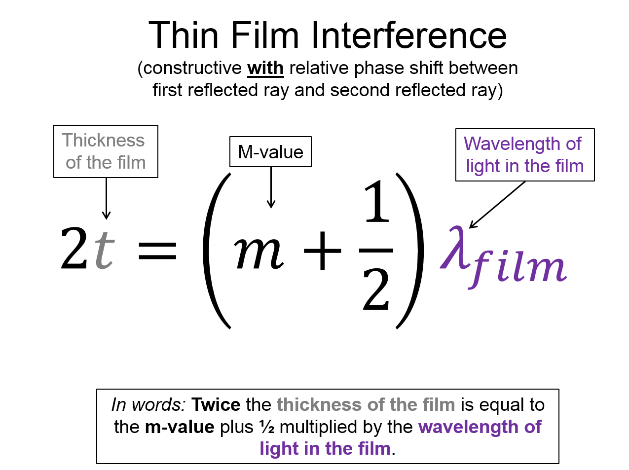
All of this means you have find the relative number of phase shifts between the first reflected wave (2) and the second reflected wave (5). An example would be the air => oil => water system described above. Oil has a higher index of refraction than oil, so ray (2) has a $\pi$ phase shift. When ray (3) reflects off the bottom surface, it is in oil and bouncing off water. Since $n_{water}<n_{oil}$ there is no phase shift in reflected ray (4) or in (5) since it is transmitted. Ray (2) and (5) are interfering but there is a relative phase shift between them. So you must switch the conditionals for constructive and destructive interference.

m = 0, 1, 2, ...  No relative phase shift ($\phi=0$)  relative phase shift ($\phi=\pi$)
 Constructive Interference  $2t = m \lambda_{film}$  $2t = (m+\frac{1}{2}) \lambda_{film}$
 Destructive Interference  $2t = (m+\frac{1}{2}) \lambda_{film}$  $2t = m \lambda_{film}$

Here $\lambda_{film}$ is the wavelength of the light in the film. You can use the index of refraction to determine $\lambda_{film}$

The most common place this effect is observed is on bubbles or oil slicks. The colors you see are because those are the wavelegths that match the conditions for more constructive interference. The colors change because there are different thicknesses in the film.

This is an image of a bubble with some material in it. There are different bands of colors because the refracted waves have different wavelengths and have some interference between the other waves that are refracted that results in the perception of different colors.                          This is an image of an oil slick where there are circular rings of different colors. This is because the are differences in thickness in the oil slick and some interference between the other waves that are refracted that results in the perception of different colors.

Key Equations and Infographics

A representation with the words index of refraction on the top. There is an equation that shows that the index of refraction is equal to the speed of light in a vacuum divided by the effective speed in a medium. This is also written in words below.

A representation with the words thin film interference on the top with a note constructive without relative phase shift between first reflected ray and the second reflected ray. There is an equation that shows that the twice the thickness of the film is equal to the product of the m-value and the wavelength of light in the film. This is also written in words below.


A representation with the words thin film interference on the top with a note constructive with relative phase shift between first reflected ray and the second reflected ray. There is an equation that shows that the twice the thickness of the film is equal to the m-value plus one half multiplied by the wavelength of the light in the film. This is also written in words below.


A representation with the words thin film interference on the top with a note destructive without relative phase shift between first reflected ray and the second reflected ray. There is an equation that shows that twice the thickness of the film is equal to the m-value plus one half multiplied by the wavelength of the light in the film. This is also written in words below.


A representation with the words thin film interference on the top with a note destructive with relative phase shift between first reflected ray and the second reflected ray. There is an equation that shows that twice the thickness of the film is equal to the product of the m-value and the wavelength of light in the film. This is also written in words below.

Now, take a look at the pre-lecture reading and videos below.

OpenStax Reading


OpenStax Section 27.7  |  Thin Film Interference

Openstax College Textbook Icon


Equations, definitions, and notation icon Concept Map Icon
Key Terms Icon Student Contributed Content Icon

Additional Study Resources

Use the supplemental resources below to support your post-lecture study.

YouTube Videos

Here is a good video on index of refraction,

https://www.youtube.com/watch?v=-aFBOcOo77Q

This is an excellent video on the refractive index,

https://www.youtube.com/watch?v=2EjtccSsFgM

Doc Schuster dives in and explains thin film interference with an example

https://www.youtube.com/watch?v=TVCsSGKqlQA

This Khan Academy video will help you understand the behavior of light as it passes through and interacts with varying index of the medium.

https://www.youtube.com/watch?v=xjMjWtntm9k

Simulations


Check out the BU thin film simulation. This is a great way to better understand the physical phenomena.

B.U. Physics Icon

For additional simulations on this subject, visit the simulations repository.

Simulation Icon

For additional simulations on this subject, visit the simulations repository.

Simulation Icon

Demos


For additional demos involving this subject, visit the demo repository

Demos Icon

For additional demos involving this subject, visit the demo repository

Demos Icon

History


Oh no, we haven't been able to write up a history overview for this topic. If you'd like to contribute, contact the director of BoxSand, KC Walsh (walshke@oregonstate.edu).

Physics Fun


Other Resources


Resource Repository

This link will take you to the repository of other content related resources.

Content Icon

Problem Solving Guide

Use the Tips and Tricks below to support your post-lecture study.

Assumptions


Checklist

1. The index of refraction is quite often used to determine how much light rays bend upon moving from one material to another. The changing directions effect is a direct consequence of the light changing effective speeds. So the first question is if the problem is about light bending at an interface or is about it changing speeds. If its about changing directions, see Snell's Law of Refraction.

2. Determine if the index of refraction is increasing or decreasing so that you know if the speed is increasing or decreasing.

3. If the problem involves wavelengths and frequencies, you may have to use the equation $v=f \lambda$. You may also have to use the fact that the frequency is constant accross a border, the wavelength and speed are not.

4. Solve for the desired quantity.

(1) Sketch out the standard representation for thin-film interference: two horizontal lines, representing 3 separate media. Label on this sketch the indices of refraction of the three media. The middle medium is the "thin film."

(2) Determine the wavelength $\lambda_2$ of your wave inside of the thin film. Remember that maximum constructive interference has to do with whether or not some integer-number of wavelengths fit into some distance, so it is important to know what the wavelength is inside of the medium in which the path-length-difference occurs - which, if you use the standard sketch, is always the middle (or second) medium.

(3a) Determine which equation is appropriate for describing constructive interference. To do this, determine whether or not there is a relative phase-shift between the two waves that are interfering. Remember that, at every boundary, some light is transmitted while some is reflected. The reflected light will have a $\pi$ phase-shift if the index of refraction of the medium the wave is traveling into is greater than that which it is leaving. Using the standard sketch, this means the wave reflected off the top surface will have a phase-shift iff $n_2 > n_1$ and the wave reflected off the second surface will have a phase-shift iff $n_3 >n_2$. Transmitted light does not undergo a phase-shift.

(3b) If there is a $\pi$ relative phase shift, then: 

  • constructive interference is described by $2t = \left(m + \frac{1}{2}\right) \lambda $, where $t$ is the thickness of the thin film and $\lambda$ is the wavelength of the light within the thin film (so here it takes the value of $\lambda_2$ calculated above, but I have left it as $\lambda$ to be consistent with other resources). 
  • destructive interference is described by $2t = m \lambda$

If there is no relative phase shift between the two waves, then the equations are swapped and $2t = m \lambda$ corresponds to constructive and $2t = \left( m + \frac{1}{2} \right) \lambda$ corresponds to destructive interference.

You now have all of the variables you need to finish the problem. Depending on the problem, you may be asked for a couple of different things. One might be a "minimum thickness" - in this case, you want to find the minimum possible value you can find for $t$, which corresponds to the smallest possible $m$ value (usually either $0$ or $1$). Or, you may be asked what wavelengths would produce destructive or constructive interference given some thickness - which is as simple as solving $2t = m \lambda$ for $t$ (or the other equation, depending on the situation). Once you have gone through step 3 above, you have all of the info that can be gleaned algorithmically: the rest is down to correctly interpreting the individual problem and what it is asking for. 

Misconceptions & Mistakes

  • ... treat the wavelength as the constant across a boundary. Frequency is what is constant across a boundary.
  • ... try and use Snell's Law for problems that only involve speed or wavelength changes. If the problem does not involve the bending of light, you do not need to use Snell's Law.
  • ... believe that a light photon actually travels slower than c. In reality if a photon (bundle of light) exists, it travels at c. In a medium there is vacuum between the atoms and that is where the photons exist. The interaction with the atoms in the medium, via mechanisms like scattering, is what makes the light take longer to travel the same overall distance.
  • ... read too much into the statement above. You can just treat the light like it's moving slower than c.
  • There is not one simple equation for thin-film interference - the conditions for maximum and minimum interference change based on the parameters of the problem. You must first determine if there are relative phase shifts!

Pro Tips

  • Sketch a simple physical representation where the wavelength of the light changes and the speeds are labeled on each side of the boundary.
  • Memorize $v=f \lambda$ and $n=\frac{c}{v_{eff}}$
  • Frequency is a property of the source, not the medium. Frequency does not change across a boundary.
  • Index of Refraction related to speed changes is taught briefly before Thin Film Interference so that you can find the wavelength in the film. If it wasn't for TFI, it would be taught in junction with Snell's Law of Refraction where it is often used as well. 
  • It's not too hard to use the concept of the speed changing across a boundary, coupled with the frequency not changing, to find the change in the wavelength. That feature, along with speed is distance over time and some geometry, makes deriving Snell's Law as a consequence of the speed changing very doable. Go through that derivation and you will have effectively mastered the concept of the index of refraction (at an introductory physics level).
  •  Always draw the same picture for thin-film interference problem: two horizontal lines, labeling the indices of refraction of the different media. This will help you get your bearings on the problem and get most of the relevant information on the page
  • Being good at thin-film interference problems is all about identifying phase-shifts, since understanding the relative phase-shift between two waves is what dictates which equations to use. Always find phase-shifts first, if you are able, before continuing on the problem.

Multiple Representations

Multiple Representations is the concept that a physical phenomena can be expressed in different ways.

Physical

Physical Representations describes the physical phenomena of the situation in a visual way.
Physical Representations describes the physical phenomena of the situation in a visual way.


Mathematical

Mathematical Representation uses equation(s) to describe and analyze the situation.

A representation with the words index of refraction on the top. There is an equation that shows that the index of refraction is equal to the speed of light in a vacuum divided by the effective speed in a medium. This is also written in words below.

A representation with the words thin film interference on the top with a note constructive without relative phase shift between first reflected ray and the second reflected ray. There is an equation that shows that the twice the thickness of the film is equal to the product of the m-value and the wavelength of light in the film. This is also written in words below.


A representation with the words thin film interference on the top with a note constructive with relative phase shift between first reflected ray and the second reflected ray. There is an equation that shows that the twice the thickness of the film is equal to the m-value plus one half multiplied by the wavelength of the light in the film. This is also written in words below.


A representation with the words thin film interference on the top with a note destructive without relative phase shift between first reflected ray and the second reflected ray. There is an equation that shows that twice the thickness of the film is equal to the m-value plus one half multiplied by the wavelength of the light in the film. This is also written in words below.


A representation with the words thin film interference on the top with a note destructive with relative phase shift between first reflected ray and the second reflected ray. There is an equation that shows that twice the thickness of the film is equal to the product of the m-value and the wavelength of light in the film. This is also written in words below.

Graphical

Graphical Representation describes the situation through use of plots and graphs.


Descriptive

Descriptive Representation describes the physical phenomena with words and annotations.


Experimental

Experimental Representation examines a physical phenomena through observations and data measurement.


Practice

Fundamental examples

(1) Light with a wavelength $\lambda = 88.7 MHz $ is broadcast through a medium with an index of refraction $ n = 3$. What is the wave speed of the broadcast?

(2) An electromagnetic wave traveling through a medium with index of refract $n= 8$ has a wavelength $\lambda = 1.8 nm$. What is its wavelength in vacuum?

(3) You are floating in a pool. Your friend thinks he is such a fast swimmer that he can beat light in a race to the other end of the pool. (your friend is not smart). The pool is 100 m long and you are at one end of it. You have a red laser pointer ($\lambda_{vac} = 700 nm$). (a) If you shine the laser pointer, underwater, long will it take for light to travel down the length of the pool? Your friend swims at a rate of 5 m/s. (b) Who will win the race? Water has an index of refraction $n_w = 1.33$.  

Solutions found HERE

Short foundation building questions, often used as clicker questions, can be found in the clicker questions repository for this subject.

Clicker Questions Icon


 (1) Green light with a wavelength $\lambda_{green} = 500 nm$ shines on a soap film (n = 1.33) that has air on either side of it. The light strikes the film perpendicularly. What is the minimum thickness of the film for which an observer would see maximum constructive interference?

(2) Orange light with a wavelength $\lambda_{OJ} = 600 nm $ shines on a soap film ($n_{soap}= 1.33$) that is resting on oil ($n_{oil} = 14 $). The top of the soap film is open to the air. What is the minimum thickness of the film for which an observer standing directly overhead would see maximum constructive interference?

(3) A glass coverslip is floating on oil in a beaker that is open to the air. The index of refraction for the glass is $n_{glass} = 2.5$ and the refractive index of the oil is $n_{oil} = 18$. Janet wants to measure the minimum thickness of the glass so she sets up a laser that will shoot light normally incident to the surface of the coverslip. The laser is capable of scanning through different wavelengths, and through clever experimentation Janet measures that the minimum thickness of the glass is 114 nm. What are two wavelengths at which Janet measured maximum constructive interference? 

Solutions found HERE.

Short foundation building questions, often used as clicker questions, can be found in the clicker questions repository for this subject.

Clicker Questions Icon


Practice Problems

BoxSand practice problems

Conceptual problems

BoxSand's multiple select problems

BoxSand's quantitative problems 

Recommended example practice problems 

  • Openstax has practice problems toward the end of each section, Website Link
  •  

For additional practice problems and worked examples, visit the link below. If you've found example problems that you've used please help us out and submit them to the student contributed content section.

Example Problems Icon