Light rays travel in straight lines until they bounces off or shines through some material. By creating diagrams that trace the rays we are able to see where images are formed, like viewing the image of yourself in the mirror.
LightXlab simulates ray diagrams for various optical configurations.
https://www.youtube.com/watch?v=AxHcLncRkbM
Pre-lecture Study Resources
Watch the pre-lecture videos and read through the OpenStax text before doing the pre-lecture homework or attending class.
BoxSand Videos
Required Videos
Ray model - Intro and assumptions(8min)
Ray model - lens of the eye(7min)
Ray model - Rough surface mirror (3min)
Ray model - Plane mirror (8min)
Converging and diverging lens basics (8min)
Suggested Supplemental Videos
Learning Objectives
Summary
Summary
Atomistic Goals
Students will be able to...
BoxSand Introduction
Ray Optics | Ray Tracing
The Ray Model of light, sometimes called Geometrical Optics, is based on the principle that light travels in straight lines until it interacts with a medium that has a different index of refraction. Rays can reflect off surfaces, bend while traveling between mediums, and cross undisturbed. To see something, the rays must go from the object to your eye. An example is seeing an object through a mirror.
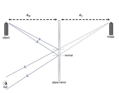
For you to see the something in a mirror, light rays must travel from the object, reflect off the mirror, and enter your eye. When you look at something through an optical element, the object appears to be located at what's called the image location. When brushing your teeth, you appear to be on the other side of the mirror because you are looking at your image. In the case of a planer mirror, the distance ($d_o$) between the object and the optical element (mirror), is the same as the distance ($d_i$) between the image and the mirror. The image is also considered a virtual image, because the rays do not actually travel through the location of the image. This can visualized by tracing two rays that diverge from the object, spreading out until hitting the mirror. They then reflect off the mirror and continue to spread out until they hit your eye. If you trace the rays back past the mirror, to where they appear to have originally diverged from, you'll find location of the image. After all, if the mirror was infinite in size and perfectly polished, you'd not know that you're looking at a image. Most illusions performed by magicians are based on images fooling the eyes.
Thin Lenses
Lenses are a common optical element found in glasses, microscopes, telescopes, and many other devices. They can be used to change the location, orientation, and size of an object's image. To use ray tracing to determine information about the image in a system with a lens, the diagram is usually drawn with a long horizontal line called the optical axis. The lens, although having some thickness, is treated like a plane perpendicular to the optical axis that redirects the rays according to the set of rules below. The object is often represented as an arrow so that the upward direction is defined. The focal point ($f$) of the lens is also drawn - the focal point is equal to half the radius ($R$) of curvature of the lens ($2f=R$).
Three Special Rays
Converging Lens
1. Parallel to the optical axis and refracts through the far focal point
2. Straight line through center of optical element
3. Through the near focal point, refracts parallel to the optical axis
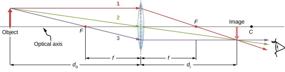
Here the distance to the object is $d_o$ and the distance to the image is $d_i$. For this distance from a converging lens with this focal point, the image is inverted and smaller in size. The image is considered a real image since the rays actually travel through the location of the image.
Diverging Lens
1. Parallel to the optical axis and refracts through as if came from near focal point
2. Straight line through center of optical element
3. Towards far focal point, refracts parallel to the optical axis
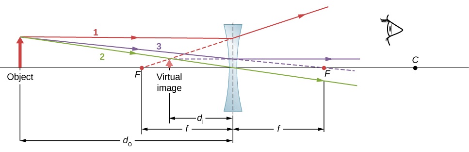
Here the ray diagram shows the image is smaller and upright. The image this time is virtual though since all the rays didn't not travel through that location. For diverging lenses the image is always virtual - you must trace backwards to find where the rays appear to have diverged from. In the diagram above you see that rays 1 and 3 had to be traced backward, denoted by the dotted lines. Converging lens can create virtual images if the object is within the focal point of the lens. For a summary of all the different ray diagrams see the PDF at the bottom of this introduction.
Key Equations and Infographics
Now, take a look at the pre-lecture reading and videos below.
OpenStax Reading
OpenStax Section 25.6 | Image Formation by Lenses
![]()
 |
Additional Study Resources
Use the supplemental resources below to support your post-lecture study.
YouTube Videos
The first introduction video will introduce concave and convex lenses and mirrors.
https://www.youtube.com/watch?v=9-XAolo9xz8
The second introduction video will describe the fundamentals of ray tracing.
https://www.youtube.com/watch?v=Jp-b8jnjrg4
The following set of videos by Doc Schuster will help you understand how to apply ray tracing.
https://www.youtube.com/watch?v=sRWlmARmxVw
https://www.youtube.com/watch?v=MZ4p9lKVIPs
https://www.youtube.com/watch?v=-WyAgyp_Tn8
https://www.youtube.com/watch?v=Bx212THhykk
https://www.youtube.com/watch?v=ScUZwLcK2pM
Simulations
Here is an excellent simulation for ray tracing with a converging lens.
![]()
For additional simulations on this subject, visit the simulations repository.
![]()
Demos
For additional demos involving this subject, visit the demo repository
![]()
History
Oh no, we haven't been able to write up a history overview for this topic. If you'd like to contribute, contact the director of BoxSand, KC Walsh (walshke@oregonstate.edu).
Physics Fun
Other Resources
LibreText has a nice explaination of thin lenses.
![]()
The Hyperphysics reference offers a straightforward approach to ray diagrams for positive (convex) and negative (concave) lenses.
![]()
Resource Repository
This link will take you to the repository of other content related resources .
![]()
Problem Solving Guide
Use the Tips and Tricks below to support your post-lecture study.
Assumptions
Checklist
Misconceptions & Mistakes
Pro Tips
- Get good at ray tracing. Ray tracing is free points on exams - these are literally the easiest points you can earn on any physics test ever. There is very little physical reasoning involved in finding the correct answer, you just need to follow a set of procedures. So take some time to get good at those procedures.
- Use graph paper
- Ray tracing is all about precision, so practice until you find ways to repeatedly find the correct image. For example, to sketch the special ray that goes through the middle of the optical axis, some people find it easier to start the ray at the optical axis and trace back to the tip of the object, and then continue the ray onto the other side of the optical element (in the case of a lens) - rather than use one stroke to trace a ray from the tip of the object, through the axis, and beyond. Different people have different mechanical skills and preferences. Figure out what works for you.
Multiple Representations
Multiple Representations is the concept that a physical phenomena can be expressed in different ways.
Physical
Mathematical
Graphical
Descriptive
Experimental
Practice
Use the practice problem sets below to strengthen your knowledge of this topic.
Fundamental examples
Use ray tracing to answer all of the following problems. For all problems:
(a) Sketch the location of the image
(b) Is the image real or virtual?
(c) Is the image larger, smaller, or the same size as the object?
(1) An object is 1m from a converging lens that has a focal length of 1.5m.
(2) An object is 1m from a diverging lens that has a focal length of 1.5m.
(3) An object is 2m away from a converging lens that has a focal length of 1.5m
(4) An object is 2m away from a diverging lens that has a focal length of 1.5m.
(5) An object is 1.5m away from a converging lens that has a focal length of 1.5m.
(6) An object is 1.5m away from a diverging lens that has a focal length of 1.5m
***The previously uploaded solutions were incorrect. Please see page 4 of the equation sheet for qualitative solutions while this is rectified***
Short foundation building questions, often used as clicker questions, can be found in the clicker questions repository for this subject.
![]()
Practice Problems
BoxSand practice problems
Conceptual problems
BoxSand's multiple select problems
BoxSand's quantitative problems
Recommended example practice problems
- Openstax has practice problems toward the end of each section, Website Link
For additional practice problems and worked examples, visit the link below. If you've found example problems that you've used please help us out and submit them to the student contributed content section.