Circuits exist in lots of everday items, from cell phones, to computers, to cars, to toasters. Anything that requires electricity to operate, has some form of circuit. Here we study circuits that have constant voltage sources, like a battery, and resistive elements, like a lightbulb.

This short video introduces simple circuits.

https://www.youtube.com/watch?v=vuCJP_5KOlI

Pre-lecture Study Resources

Watch the pre-lecture videos and read through the OpenStax text before doing the pre-lecture homework or attending class.

BoxSand Videos

Learning Objectives

Summary

Summary

Atomistic Goals

Students will be able to...

  1.  

BoxSand Introduction

Subject  |  Lecture


Basic circuit analysis - energy and power

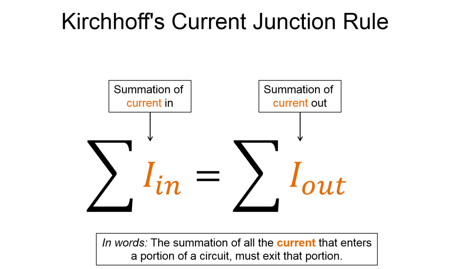
While constructing our microscopic model of charge we ran into the idea of conservation of charge. Here, conservation of charge states that the amount of charge that reaches the cross-sectional area in a given unit of time, must also leave that cross-sectional area in the same amount of time. This should make some intuitive sense, for example, if more charge enters the cross-sectional area than leaves it, then charge would build up on the cross-section. If charged built up on the cross-sectional area, then it would begin to repel the incoming charge thus reducing the current until it eventually stops. Basically, conservation of charge will ensure that our current is constant.

In this section, we will look more closely at this statement by practicing some problems that highlight how conservation of charge is used in analyzing current flowing through circuits. Before we dive into the questions, we should first define a commonly used term, junction. A junction is a location where current coming from one direction can be split into two or more directions. Luckily there is a concrete analogy we can rely on; an intersection of a road. Just like driving, if you come to a location where you have an option to go left or right, you could call that location a junction.

Batteries?

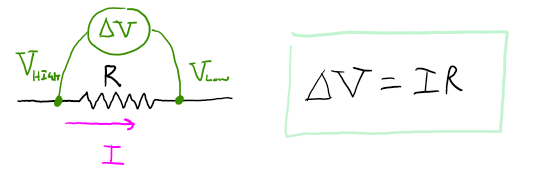
Recall that to establish a current in a wire we must create an electric field inside the wire that pushes the free electrons around inside the conductor's lattice. An equally valid statement is: to establish a current in a wire we must create an electric potential gradient (e.g. a voltage gradient) within the wire that the electrons will move up in. Remember that positive charges move down in electric potential while negative move up in electric potential. To create this electric field, or electric potential gradient, we needed to establish a non-uniform surface charge distribution along the wire. One method of creating this non-uniform surface charge distribution is to attach two places, one positive, and one negative to a wire as shown below.

This is an image of two curved wires facing each other in a square formation with a plate attached to one end of both wires and the other end connected. The left wire is negatively charged and has a negative voltage and the right wire is positively charged with a positive voltage and both wires have a non-uniform surface charge distribution.

As you can imagine, the plates each have a finite amount of excess charge on them, and eventually the system will reach an electrostatic equilibrium. After all, the surface charges on the wire are free to move along the surface of the wire. If we could physically stand in-between the two plates above and constantly move some negative charge from the left plate onto the right plate, we could maintain the charge separation on the plates and thus maintain the non-uniform surface charge distribution (e.g. maintain the current). This is of course impractical, how do we grab free electrons and move them from one plate to the other? Perhaps there are other methods commonly used. In fact there are. Below is a list of a few ways we can separate charge, and thus they are ways which we could maintain the current within the figure above.

A few ways to separate charge

  • Mechanically
    • How?...  charge transfer by friction, charge transfer by induction, charge transfer by contact
    • Applications:  Van De Graff Generator
  • Chemically
    • How?... many different ways, consult chemistry text
    • Applications:  batteries
  • Solar
    • How?... do some research smiley
    • Applications:  solar panels
  • Electromagnetically
    • How?... will cover soon
    • Applications:  will cover soon


Let's take closer look at batteries since we will be using them most often for separating charge and maintaining that non-uniform charge distribution.

  • Ideal battery - An ideal battery is a source of constant electric potential difference between its two terminals (i.e. a constant voltage difference) where the work done by the chemicals within the battery all goes towards the increase in electric potential energy of the free charges.
    • The chemical reactions within the battery separate charge. In other words, the chemical reactions within the battery do work on the free electrons to move them from low electrical potential energy to high electrical potential energy.
      • The amount of work per unit charge that the battery does in moving electrons from low to high electrical potential energy is referred to as the "emf" of the battery. We use the symbol Ɛ for emf.
        • Be careful, historically the "emf" was referred to as the "electromotive force", but note that it is not a force at all. It has units of energy/charge.
        • Below is a physical representation of an ideal battery where the emf is the terminal voltage regardless if the battery is connected to a load or not (i.e. regardless if it is connected to a resistor, or lightbulb, etc..).
          • Key points:
            • The battery move free electrons, via chemical reactions, from regions of high voltage where the electric potential energy of the electrons is low, to regions of low voltage where the electric potential energy of the electrons is high. Remember that naturally, electrons will "fall up in potential" thus work must be done to move them "down in potential".
            • As the electrons then naturally "fall up in potential" along the length of the wire, the electrons lose their electric potential energy to the thermal energy of the wire and resistor. The energy transfer from electric potential energy to thermal energy of the wire is typically very small compared to resistors and lightbulbs, thus we typically ignore the effects of the wire and only look at elements such as resistors and lightbulbs.
            • The terminal voltage is the emf of an ideal battery.

This is an image of a voltage meter connected to a battery that is also connected to a resistor. The red wire of the voltage meter is connected to the positive end of the battery and the black wire is connected to the negative end and both ends of the batteries are connected to another wire with a resistor in the center. The terminal voltage difference is noted as the change in the voltage of the batter is equal to the high voltage minus the low voltage. On the positive end of the battery, there is a low electrical potential energy with the current going up and a high voltage and the negative end of the battery has a low voltage and a high electrical potential energy. The electrons exit the negative end of the battery, goes through the resistor where the change in electrical potential energy is related to the change in thermal energy of the resistor and then to the positive end of the battery. The current is going in the opposite direction of the flow of electrons.

  • Ideal real battery - An ideal real battery is a source of constant electric potential difference between its two terminals (i.e. a constant voltage difference) where the work done by the chemicals within the battery partially goes towards the increase in electric potential energy of the free charges and partially towards an increase in thermal energy of the battery.
    • The chemical reactions within the battery separate charge. In other words, the chemical reactions within the battery do work on the free electrons to move them from low electrical potential energy to high electrical potential energy. These chemical reactions also increase the thermal energy of the battery. Thus, not all of the work from the chemical reactions is used to increase the electric potential energy. The increase in thermal energy is accounted for by using an "internal resistance" (typically labeled "r"), connected to an ideal battery. The combined ideal emf and internal resistance then make up this ideal real battery.
    • Below is a physical representation of an ideal real battery 
    • Key points:
      • When there is no load on the battery (i.e. when there is no resistor, lightbulb, etc. connected to the battery), the terminal voltage is the emf of an ideal battery ® When current is drawn from the battery, (i.e. when there is a resistor, lightbulb, etc. connected to the battery) then the terminal voltage of the ideal real battery drops slightly because not all of the work from the chemicals is used to increase the electric potential energy; some of the work is used to increase the thermal energy of the battery. This is why batteries get warm to the touch when they are used in circuits.

This is an image of a voltage meter connected to a battery that is also connected to a resistor. The red wire of the voltage meter is connected to the positive end of the battery and the black wire is connected to the negative end and both ends of the batteries are connected to another wire with a resistor in the center. With no load, the change in voltage is equal to the electric potential and with load in example, with a current, the change in voltage of the battery is equal to the electric potential subtracted by the current multiplied by the internal resistance r.

  • Real battery - It turns out that the internal resistance of the battery is not a constant. The internal resistance is typically a function of current. The more current that is going through the battery, the higher the internal resistance is. Thus if you draw too large a current from a real battery, the internal resistance can get so high as to cause the battery to get very hot. Most text use "real battery" when they in fact mean "ideal real battery". However, I like to make the distinction between the two.


In general, notice that the symbol for an ideal battery is two parallel lines, with one a bit longer than the other. The longer line is conventionally representing the positive end of a battery, and the shorter is representing the negative end.

POWER

It is often useful to use power to characterize circuits and/or circuit elements such as resistors and lightbulbs. Recall that power is energy/time. For example, if we knew how much power a light bulb dissipates as thermal energy, along with the total stored chemical energy in a battery, we could determine the total time the battery could light up the bulb until the chemicals can no longer supply the necessary voltage difference. Power is also a useful quantity when trying to make a connection between electronics and more familiar mechanical systems. For example, knowing just the current, resistance, or change in voltage across lightbulbs might not be as insightful as comparing the power dissipated by the lightbulb to the power required to run up a flight of stairs. Basically, it's a useful quantity that can connect some of the intangible electric phenomena to tangible mechanical phenomena.

Below is a brief mini derivation of how to calculate power

The general equation for power is power is equal to energy over time. Recall that the change in electric potential energy is equal to the charge multiplied by the change in voltage and divided by the change in time and recalling that the current is equal to the change in charge divided by the change in time, this results in the change in electric potential energy divided by the change in time which is equal to the current multiplied by the change in voltage. So the electrical power is equal to the current multiplied by the change in electrical potential or change in voltage. Or with Ohm’s law this equation can be transformed into electrical power is equal to the change in voltage squared divided by the resistance which is useful when the change in voltage is constant. Or this equation can be transformed into electrical power is equal to current squared multiplied by the resistance which is more useful when the current is constant.

Looking at the above three expressions, we can begin to see which one is most useful to use in certain situations. For example, if the current through multiple resistors is constant, then using the last expression for power is most useful because it directly relates power to only current and resistance. Basically, the two expressions on the right side of the arrow are useful because Ohm's law was already used when constructing them. This simplifies an analysis by making most problems a single proportional reasoning step, where it would otherwise be two proportional reasoning steps to get to the same conclusion.

Recall that one way to characterize how humans perceive sound is by "loudness". Remember that the loudness was related to the intensity of the sound wave. Similarly, one way to characterize how humans perceive light is by "brightness". Following the same analogy, the brightness of a light is related to the intensity of the light. Remember that intensity is power/area. So if we wanted to talk about how bright a lightbulb is relative to another lightbulb, given a fixed distance away (i.e. constant area), then we could use the power of the lightbulbs to compare their relative brightness. Much like sound, there are other features of light that affect our perception of it, for example the frequency. However, for most circumstances, using power to rank relative brightness is a valid first approximation.


Ohm's law

The amount of current flowing through an ohmic element multiplied by the resistance of that element, is equal to the change in voltage across the element.

This is an image of a resistor with a current moving from left through the resistor and to the right. The voltage is high on the left side of the resistor and the voltage is low on the right side of the resistor. The difference between the voltage or before and after the resistor is the change in voltage. The change in voltage is equal to the current multiplied by the resistance.

Recall that Ohm's law does not apply to all circuit elements, only to those that are "ohmic devices" such as resistors. Some lightbulbs can be modeled relatively well with Ohm's law but not all. For our class we will assume all light bulbs are able to be modeled with Ohm's law. Capacitors and inductors cannot be modeled with Ohm's law.


Kirchhoff's Junction law

The total current that enters into a cross-sectional area, must also exit out of that cross-sectional area.

This is an image of example of a circuit where the battery is in a loop and at one point in the loop it splits and passes through two resistors R one and R two and meets back together to meet back at the battery. The current at the split is shown as the equation the sum of the current in is equal to the sum of the current out  so that the total current is equal to the current of one plus the current of two. The current at the merge back together is shown as the equation the sum of the current in is equal to the sum of the current out so that the current of one plus the current of two is equal to the total current. Although there are two junctions, there is only one unique equation where the sum of the currents in is equal to the sum of the currents out.

This junction law is just a restatement of conservation of charge as discussed previously. Remember that if conservation of charge were not true, then charge would build up at a location within the circuit and the current would eventually stop.


Kirchhoff's voltage loop law

The sum of all the voltage differences across each element along a closed loop is equal to zero.

This is an image of a circuit where there is an electrical source and the current travels up and clockwise through resistor one and resistor two and back to the source. The sum of the change in the voltage loop is equal to zero so that the change in voltage of the battery plus the change in voltage at resistor one plus the change in voltage at resistor two is equal to zero. From there, the equation expanded is the battery minus the current multiplied by resistor one minus the current multiplied by resistor two is equal to zero. The net change in voltage of the loop is equal to zero.

The voltage loop rule is really just a restatement of conservation of energy. Recall that the electric potential energy is a function of position, thus if your initial and final positions are the same, the change in energy is zero. Then, by using the definition of electric potential, you should clearly see that the change in potential is also zero.

Note that you get to choose the direction of the loop. In the example above I choose a loop going clockwise, however using a counter-clockwise loop will result in an equally valid equation. Below are the conventions for loops and signs of voltage differences.


Conventions for loop law

This is a representation of different ways of showing batteries and resistors. For a battery, it is drawn as two parallel lines with the right line longer than the left and the battery is denoted with the symbol epsilon. The first scenario shows the current loop moving from left to right so that the change in voltage is equal to positive electrical potential energy and the negative of that is true if the current loop was moving from right to left. For resistor, they are drawn as a series of squiggly lines up and down. The first scenario shows the current loop moving from left to right so that the change in voltage is equal to the negative current multiplied by the resistor and the negative of that equation is true of the current loop was moving from right to left.

As seen above, the convention for the voltage difference across a battery is determined only by the direction of the loop you defined. If your loop is going from the negative side of the battery to the positive side, then the change in voltage is positive. This is true regardless if the current is going in the same or opposite direction.

As seen above, the convention for resistors is a bit more tricky than batteries. Since resistors don't have an inherent a positive and negative side we use the direction of current relative to the direction of the loop to define a positive or negative change in voltage. If the loop is in the same direction of current going through the resistor, then the change in voltage is negative.


Key Equations and Infographics

A representation with the words Ohm’s law on the top. There is an equation that shows that the change in voltage is equal to the current multiplied by the resistance. This is written in words below.


A representation with the words Kirchhoff’s Voltage Loop law on the top. There is an equation that shows that the summation of the voltage changes around a closed loop is equal to zero. This is also written in words below.


A representation with the words Kirchhoff’s current junction rule on the top. There is an equation that shows that the summation of all the current that enters a portion of a circuit, must exit that portion. This is also written in words below.

Now, take a look at the pre-lecture reading and videos below.

OpenStax Reading


OpenStax Section #.# | Title -- From Fundamentals

Openstax has a section each for Ohm's Law and Simple Circuits, and Kirchhoff's Rules.

Ohm's Law: Resistance and Simple Circuits Kirchhoff's Rules
Openstax College Textbook Icon Openstax College Textbook Icon


Equations, definitions, and notation icon Concept Map Icon
Key Terms Icon Student Contributed Content Icon

Additional Study Resources

Use the supplemental resources below to support your post-lecture study.

YouTube Videos


Doc Schuster introduces resistance, resistors and resistivity.

https://www.youtube.com/watch?v=XoI6QmQeAXo

Pre-Med Academy covers Ohm's Law and Kirchhoff's Laws. 

https://www.youtube.com/watch?v=98ia97LE1tQ

https://www.youtube.com/watch?v=JE2091q_u5Q

Here's a pretty basic example from Carl Oliver's youtube.


https://www.youtube.com/watch?v=qAXVtuptW_w


Step-by-Step Science has quite a few videos on using Kirchhoff's Current and Voltage Rules (playlist here), here are a couple of the examples,


Youtube: Step by Step Science - Kirchhoff 1


Youtube: Step by Step Science - Kirchoff 2


Other Resources

This link will take you to the repository of other content related resources .

Content Icon

Simulations


This PhET interactive allows you to see how the equation form of Ohm's law relates to the simple circuit. Adjust the voltage and resistance and see how current changes in accordence with Ohm's law

Phet Interactive Simulations Icon

This PhET is their Circuit Construction Kit. See if you can use Ohm's and Kirchhoff's Laws to predict behavior in the circuit for certain values.

Phet Interactive Simulations Icon

For additional simulations on this subject, visit the simulations repository.

Simulation Icon

Demos


For additional demos involving this subject, visit the demo repository

Demos Icon

History


Oh no, we haven't been able to write up a history overview for this topic. If you'd like to contribute, contact the director of BoxSand, KC Walsh (walshke@oregonstate.edu).

Physics Fun

This short video introduces simple circuits.

https://www.youtube.com/watch?v=4SIT0aU_FRw&ab_channel=LambertFowles

Other Resources


Resource Repository

Boston University's has two reference pages for Ohm's Law and Kirchhoff's Laws


Ohm's Law Kirchhoff's Rules
B.U. Physics Icon B.U. Physics Icon

Isaac Physics' has a short section on Ohm's law and then a longer section with a few examples for Kirchhoff's laws.

Ohm's Law Kirchhoff's
Other Content Icon Other Content Icon

Here are a couple of quick references, the first is from Hyperphysics covering Ohm's Law, the second is from the University of Winnipeg and covers Kirchhoff's Laws.

Ohm's Law Kirchhoff's Law
Hyper Physics Icon Other Content Icon

PPLATO is a complete resource with a lot of information, and several practice questions per subject. This webpage coveres electric current and Circuits, which includes Ohm's and Kirchhoff's laws.

Other Content Icon

Other Resources

This link will take you to the repository of other content related resources .

Content Icon

Problem Solving Guide

Use the Tips and Tricks below to support your post-lecture study.

Assumptions


Checklist


Misconceptions & Mistakes


Pro Tips


Multiple Representations

Multiple Representations is the concept that a physical phenomena can be expressed in different ways.

Physical

Physical Representations describes the physical phenomena of the situation in a visual way.


Mathematical

Mathematical Representation uses equation(s) to describe and analyze the situation.

A representation with the words Ohm’s law on the top. There is an equation that shows that the change in voltage is equal to the current multiplied by the resistance. This is written in words below.


A representation with the words Kirchhoff’s Voltage Loop law on the top. There is an equation that shows that the summation of the voltage changes around a closed loop is equal to zero. This is also written in words below.


A representation with the words Kirchhoff’s current junction rule on the top. There is an equation that shows that the summation of all the current that enters a portion of a circuit, must exit that portion. This is also written in words below.

Graphical

Graphical Representation describes the situation through use of plots and graphs.


Descriptive

Descriptive Representation describes the physical phenomena with words and annotations.


Experimental

Experimental Representation examines a physical phenomena through observations and data measurement.


Practice

Use the practice problem sets below to strengthen your knowledge of this topic.

Fundamental examples


(1) (a) You have a simple circuit that consists of only a battery ($\Delta V_{bat} = 1.5 V$) and a resistor with resistance $R_1 = 10 \Omega$ What is the current running through the battery?

(b) You add an additional resistor in series to your circuit in part A. The resistance of this second resistor is identical to the first. What is the current running through the battery?

(c) You re-arrange your circuit so now $R_2$ is attached in parallel to $R_1$ rather than in series. What is the current running through the battery?

(2) (a) You have a simple circuit that consists of only a battery ($\Delta V_{bat} = 1.5 V$) and two resistors with resistance $R_1 = 10 \Omega$ and $R_2 = 5 \Omega $, connected in series with each other.  What is the current running through the battery?

(b) You re-arrange your circuit so now $R_2$ is attached in parallel to $R_1$ rather than in series. What is the current running through the battery?

(c) You add an additional resistor $R_3 = 7 \Omega$ on the same branch as $R_2$. What is the current running through the battery?

(d) What is the power dissipated in $R_3$?

While we continue to work on making custom content check out these two guided exercises from the University of Wisconsen-Green Bay. 

  • University of Wisconsin-Green Bay

Short foundation building questions, often used as clicker questions, can be found in the clicker questions repository for this subject.

Clicker Questions Icon


Practice Problems

BoxSand practice problems

BoxSand's multiple select practice problems

BoxSand's conceptual practice problems

BoxSand's quantitative practice problems

Recommended example practice problems 


For additional practice problems and worked examples, visit the link below. If you've found example problems that you've used please help us out and submit them to the student contributed content section.

Example Problems Icon