This section will introduce perhaps the most fundamental principle in our studies of fluid mechanics, Bernoulli’s principle. It is a direct application of conservation of mechanical energy density and proves useful for both fluid dynamics and fluid statics. Bernoulli’s equation and the continuity equation are usually the two most useful tools when approaching a fluid mechanics problem.
This OpenStax physics trailer provides real life examples of Bernoulli's equation in action.
Pre-lecture Study Resources
Watch the pre-lecture videos and read through the OpenStax text before doing the pre-lecture homework or attending class.
BoxSand Introduction
Fluid Dynamics | Continuity and Bernoulli's Principle
How often are weather reports accurate? Sometimes it feels like they can never get the forecast right. Why is this? Well, the dynamics of our atmosphere fall under the realm of fluid dynamics, which means predicting the future (predicting the weather) requires solving fluid dynamic equations. Just like our early studies of kinematics, fluid dynamic equations require initial conditions, however, unlike kinematics, a very small change in the initial conditions can lead to a very different final answer in fluid dynamics. Basically, the study of fluid dynamics is very complicated.
Luckily we are able to make a few approximations which will allow us to quantify some aspects of fluids in motion. Our first approximation is restricting ourselves to only study fluids that move in a certain way. Consider two locations A and B within a tube of moving fluid as shown in the left image of the figure below. Our model of the moving fluid will assume that any particle that passes through location A will follow a unique path to get to location B. That unique path is represented by the dashed line between location A and B.

Similarly, if we look at other locations such as C and D, a particle passing through each will also follow unique paths and no paths cross each other. This type of fluid flow is called laminar flow (or smooth flow). For comparison, the right image of the figure above shows turbulent flow where particles in the fluid that pass through each point follow chaotic paths that change in time, this makes the future position of each particle extremely hard to predict.
Furthermore, if we make another assumption and ignore viscous forces (internal friction between "layers" of fluid and external friction between the fluid and the walls of the tube) then the velocity profile (the speed at every location along the cross section of a cylindrical of the tube) is constant. If this were not the case, then kinetic energy of the fluid near the surfaces of the tube would be lost to thermal energy because of the viscous forces (this would mean larger velocities in the center of the tube and velocities approaching zero at the edges). Below is a simplified velocity profile comparison between inviscid flow (without viscous forces) and viscous flow (with viscous forces).

Our third assumption is that the fluid is incompressible, or in other words, that the fluid's density is a constant.
When combined, all three of these approximations allow us to make the following statement, "the mass of fluid that enters a certain region in a given amount of time is equal to the mass of fluid that leaves another region in the same amount of time." This is known as the continuity of mass flow rate. Mathematically we write this as...
$\sum{\dot{m}}_{in}$ $=$ $\sum{\dot{m}}_{out}$ where $\dot{m} = \rho \, v \, A$ and $v$ is the speed, $A$ is cross sectional area
What the the continuity equation above says is, "what goes in at some rate, must come out at the same rate".
If there we restrict our studies to only one type of fluid in a tube at a time, then density is a constant and we use volume flow rate, $Q$...
$Q = \frac{\dot{m}}{\rho} = v \, A$
Then our continuity equation becomes...
$\sum{Q}_{in} = \sum{Q}_{out}$
Bernoulli’s equation relates the speed, relative height, and pressure at any location within a moving or stationary fluid. Bernoulli’s equation and the continuity equation are usually the two most useful tools when approaching a fluid mechanics problem. Before defining Bernoulli’s equation, a simple derivation will help demystify its appearance.
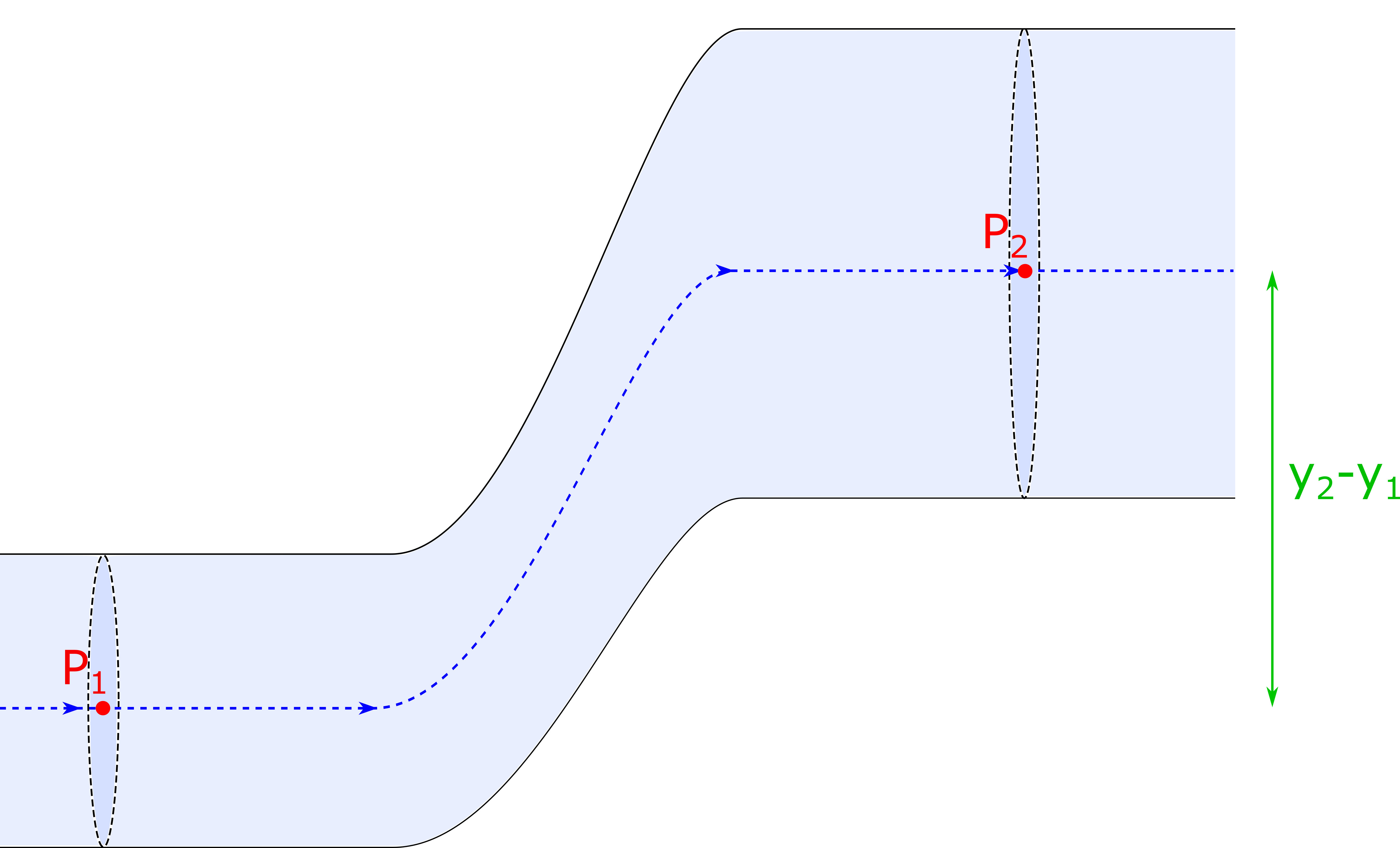
Consider the figure below which shows a moving fluid inside a tube that changes height and radius. We will consider an ideal fluid, (i.e. laminar flow, no viscous forces, and incompressible). The pressure is measured at the center of each cross sectional area as indicated by the red $P_1$ and $P_2$. The dashed blue line indicates the stream line that passes through the two locations we will consider.
Let’s apply conservation of mechanical energy to this system.
$\sum{E}_1 + W_{nc} = \sum{E}_2$
Here we are ignoring any thermal energy since changes in temperature are typically very small in the scenarios we will study.
Some algebraic manipulations and we get our conservation of mechanical energy into the form below..
$\Delta KE + \Delta U^g = W_{nc}$
Each of the above terms have the following form…
$\Delta KE = \frac{1}{2} m \, \Delta v^2 = \frac{1}{2} \rho \, V \, \Delta v^2$ where $v$ is velocity and $V$ is volume.
$\Delta U^g = m \, g \, \Delta y = \rho \, V \, g \, \Delta y$ where $V$ is volume.
$W_{nc} = | \vec{F} | \, \Delta x = \Delta P \, A, \Delta x = \Delta P \, V$ where $A$ is cross sectional area and $P$ is pressure
In the expression for the non-conservative work, force is the force due to the horizontal pressure gradient within the fluid.
Note that all the expressions contain the volume $V$, so let’s substitute each expression back into the conservation of mechanical energy and divide by volume.…
$\frac{1}{2} \rho \, \Delta v^2 + \rho \, g \, \Delta y = \Delta P$
Note that each term has units of energy per volume, thus this is a now a statement of conservation of mechanical energy density. One more algebraic manipulation and we get the familiar form which we call Bernouill’s principle…
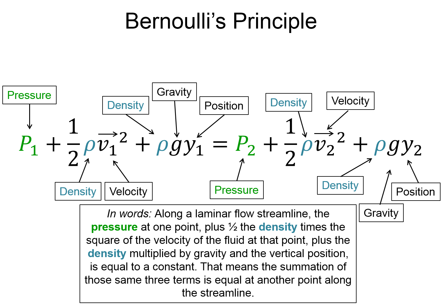
$P_{1} + \frac{1}{2} \rho \, v^{2}_{1} + \rho \, g \, y_{1} = P_{2} + \frac{1}{2} \rho \, v^{2}_{2} + \rho \, g \, y_{2} = constant$
Key Equations and Infographics


Now, take a look at the pre-lecture reading and videos below.
BoxSand Videos
Required Videos
Fluids Dynamics - assumptions(3min)
Fluids Dynamics - continuity(6min)
Fluids Dynamics - velocity fields(7min)
Fluids Dynamics - Bernoulli Intro(4min)
Fluids Dynamics - Bernoulli(9min)
Suggested Supplemental Videos
OpenStax Reading
OpenStax Section 12.1 | Flow Rate and Its Relation to Velocity
OpenStax Section 12.2 | Bernoulli's Equation
OpenStax Section 12.3 | The Most General Applications of Bernoulli's Equation
Fundamental examples
1. A faucet is capable of filling a $1 \, L$ bottle in $10$ seconds. If the diameter of the piping in the house is $12.7 \, mm$, what speed does the water flow inside the pipes?
2. A $1 \, cc$ syringe attached to a $25$ gauge needle is shown in the figure below with the dimensions labeled. If the plunger of the syringe is pushed with a speed of $10 \, mm/s$, at what speed does the fluid inside the syringe leave the tip of the needle?

3. The diameter of a typical garden hose is $0.625 \, inches$ and contains water that flows at a speed of $1 \, m/s$. What diameter nozzle must you connect to the end of the hose to get the water to shoot out with a speed of $10 \, m/s$ ?
CLICK HERE for solutions
Short foundation building questions, often used as clicker questions, can be found in the clicker questions repository for this subject.
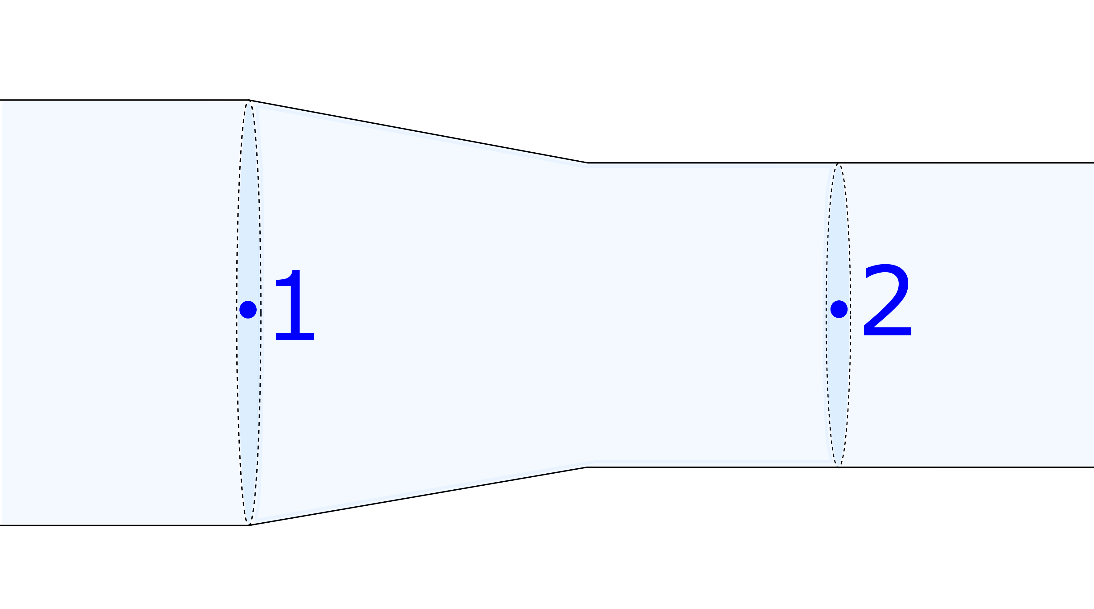
1. Consider the figure below. The pressure drops $5 \, kPa$ from location 1 to location 2. The speed of the water at location 1 is known to be $3.87 \, m/s$. What is the speed at location 2?
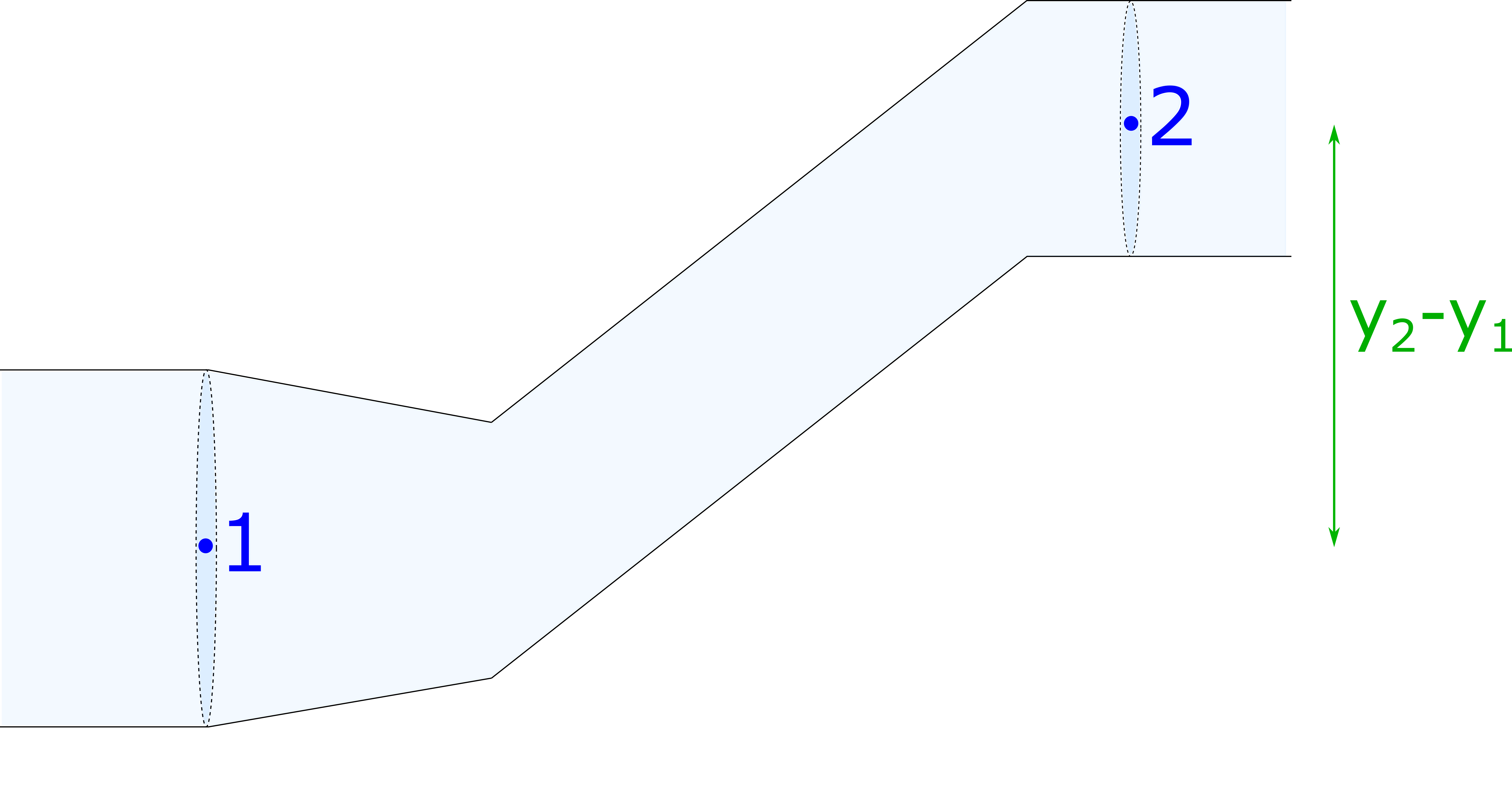
2. Consider the figure below. The pressure drops $5 \, kPa$ from location 1 to location 2. The speed of the water at location 1 is equal to the speed at location 2. What is the change in height between these two locations?
3. Consider the figure below. The pressure drops $5 \, kPa$ from location 1 to location 2. The diameter of the pipe at location 1 is $3 \, cm$ and at location 2 is $2 \, cm$. What is the speed of the water at each location?

CLICK HERE for solutions.
Short foundation building questions, often used as clicker questions, can be found in the clicker questions repository for this subject.
Post-Lecture Study Resources
Use the supplemental resources below to support your post-lecture study.
Practice Problems
BoxSand practice problems
Conceptual problems
BoxSand's multiple select problems
BoxSand's quantitative problems
Recommended example practice problems
- Openstax section on the Flow Rate has practice problems at the bottom, Website Link
- 4 questions, Website Link
- 8 questions with key, PDF Link
For additional practice problems and worked examples, visit the link below. If you've found example problems that you've used please help us out and submit them to the student contributed content section.
Additional Boxsand Study Resources
Additional BoxSand Study Resources
Learning Objectives
Summary
This section will introduce perhaps the most fundamental principle in our studies of fluid mechanics, Bernoulli’s principle. It is a direct application of conservation of mechanical energy density and proves useful for both fluid dynamics and fluid statics. Bernoulli’s equation and the continuity equation are usually the two most useful tools when approaching a fluid mechanics problem.
Atomistic Goals
Students will be able to...
- Match algebraic symbols to conceptual quantities in the continuity equation for fluid flow.
- Use proportional reasoning arguments to explore the relationship between velocity and cross-sectional area using the volume flow rate equation.
- Match algebraic symbols to conceptual quantities in Bernoulli's equation.
- Identify Bernoulli's equation as a statement of energy density conservation.
- Use proportional reasoning arguments to explore the relationship between quantities in Bernoulli's equation.
- Identify and reason with units and dimensions of quantities related to fluid dynamics.
- Differentiate between the volume flow rate and the velocity of a fluid.
- Algebraically analyze fluid flow using the continuity equation.
- Algebraically analyze fluid flow using Bernoulli's equation.
- Synthesize continuity arguments with Bernoulli's equation arguments to conceptually analyze a fluid in motion.
- Synthesize the continuity equation concepts with Bernoulli's equation concepts to make algebraic arguments about a fluid in motion.
YouTube Videos
We will now begin to study the properties of moving fluids. In general, this is a very complicated task which would require calculus and perhaps one or more courses that are solely focused on the field fluid dynamics. In this section, we will apply a few approximations with regards to the moving fluid and study the consequences that arise, namely the continuity equation.
This is a very good video lecture on continuity which brings in a connection with biology.
https://www.youtube.com/embed/wykn-JTnacE?rel=0
Bozeman Physics gives the usual clear description of continuity in this lecture.
Other Resources
This link will take you to the repository of other content related resources .
Robert Ayton gives a very good lecture covering the Bernoulli Principle
https://www.youtube.com/embed/QWEq3xifCDw?rel=0
This 3D Animation shows Bernoulli's Principle in effect
Other Resources
This link will take you to the repository of other content related resources .
Simulations
In this simple simulation, pay attention to the speed at which the tracked particles move through the pipes with different diameters.
For additional simulations on this subject, visit the simulations repository.
In this simple simulation you can see the effect of the Bernoulli Principle on water passing through a tube of different diameters. Think back to the simulation in the continuity section for when the Bernoulli Principle is not taken into account.
For additional simulations on this subject, visit the simulations repository.
Demos
For additional demos involving this subject, visit the demo repository
Box Fall Experiment - Why does this box fall as I walk past? I do not touch it.
For additional demos involving this subject, visit the demo repository
History
Oh no, we haven't been able to write up a history overview for this topic. If you'd like to contribute, contact the director of BoxSand, KC Walsh (walshke@oregonstate.edu).
Physics Fun
Other Resources
Flow rate and continuity is also covered in this section of Boundless
NASA just so happens to have a page which covers mass flow rate and how it affects their lives
This page from the University of Winnipeg is a short and sweet covering of flow rate and continuity
Other Resources
This link will take you to the repository of other content related resources .
This is the Boundless section for Bernoulli's Principle
This website covers Bernoulli's Principle and has various animations
Here's the Hyperphysics reference sheet for Bernoulli's Principle
This is a fun activity involving a bird paper plain and connections to Bernoulli's Principle
Other Resources
This link will take you to the repository of other content related resources .
Resource Repository
This link will take you to the repository of other content related resources.
Problem Solving Guide
Use the Tips and Tricks below to support your post-lecture study.
Assumptions
Fluids is typically one of the more confusing topics for students, but it can be made easier by a couple steps.
1) Know if you're dealing with a static or dynamic fluid. This should be easy enough, just ask yourself if the water is flowing or stationary in the problem.
2) Finding the avalible equations.
For dynamic fluids, there are only two, Bernoulli's and Continuity. Bernoulli's is a beast, but usually some terms are 0 that you can pick out immediately. Keep in mind Continuity can be plugged into Bernoulli because they both have velocity in them, but this will only happen when water is flowing in a pipe and changes both pipe diameter and pressure/height of the pipe.
For static fluid problems, there is really only the defnition of pressure, pressure at depth, bouyant force and density. This is more complicated and can incorporate a couple extra tricks, but generally having all these written down and tracing what you know should give you a map to finding the correct answer. The other other tricks to this are drawing Free Body Diagrams with Buoyant force in them and realizing where pressures are equivalent (along any horizontal line in a fluid or at any point interacting with a piston in hydraulics problems.
Checklist
1. Read and re-read the whole problem carefully.
2. Visualize the scenario. Mentally try to understand what the problem is asking (think about the geometry, such as circles, rectangles, etc... that the problem might be asking about).
3. Draw a physical representation of the scenario, this may include a picture of an object with labeled dimensions.
4. Determine the volume flow rate $Q$ at each location of interest.
5. Set each location's volume flow rate equal to each other.
6. Identify all the knowns and unknowns.
7. Carry out the algebraic process of solving the equation.
8. Evaluate your answer, make sure the units are correct and the results are within reason.
Misconceptions & Mistakes
- Although we often write the volume flow rate as $Q = v \, A$, remember that the $v$ in this case is a speed not a velocity.
- When an tube that contains moving fluid changes height and diameter, the pressure at the higher location is not necessiarly lower than the bottom location. As seen in Bernoulli's equation, it depends on buth the change in height and the change in cross sectional area.
Pro Tips
- First determine the volume flow rate $Q$ for each location of interest. Then apply continuity and set the volume flow rate at each location equal to each other.
- Draw a physical representation labeling all dimensions, speeds, and pressures at the specific locations of interest.
- If applying Bernoulli's principle results in 1 equation and 2 unknowns, try applying continuity to come up with a second equation.
Multiple Representations
Multiple Representations is the concept that a physical phenomena can be expressed in different ways.
Physical
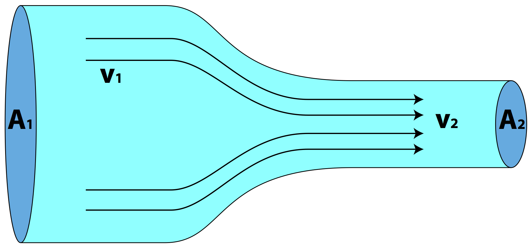
The velocity of a fluid flowing through an enclosed area is dependent on the cross sectional area of the enclose area. Below, the velocity of the fluid changes with the geometery of the enclosure.
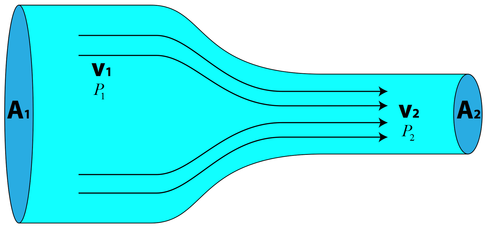
The velocirty of the liquid flowing through the enclosed system below is dependent on the geometry, pressure, and potetntial energy.
Mathematical
$\sum Q_{in} = \sum Q_{out}$
$\sum \rho V_{in} = \sum \rho V_{out}$
Heat ($Q$), Velocity ($V$), Density of fluid ($\rho$)


$P + \rho g y+ \frac{1}{2} \rho v^{2}= Const.$
$P_{1}+ \rho g y_{1} +\frac{1}{2} \rho v_{1}^{2}=P_{2}+ \rho g y_{2} +\frac{1}{2} \rho v_{2}^{2}$
The equation above reads: The pressure plus the potential energy per unit volume plus the kinetic energy per unit volume, is constant along a stream line .
Continuity: $\sum A_{1}v_{1}=\sum A_{2}v_{2}$
Pressure($P$), Density of fluid ($\rho$), Gravity ($g$), Height ($y$), Velocity ($v$), Area ($A$)

Graphical
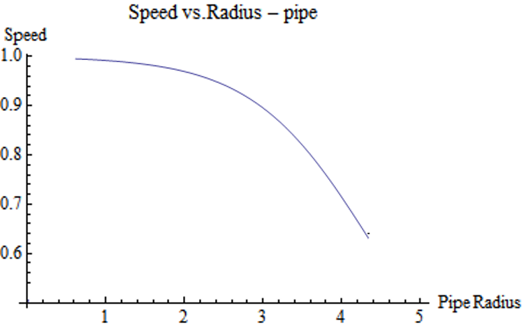
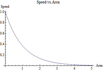
The left graph describes the speed of a fluid with respect to the diameter of a pipe. As the size of the pipe increases, the speed of the fluid decreases. Similarly, the graph on the right depicts the speed with respect to the area of the enclosure.
Descriptive
Continuity describes the flow rate of a fluid flowing through a confined space. The amount of fluid going in must match the amount of fluid flowing out. Therefore, as the geomety of the confined space change so must the speed of the fluid in order to maintain a constant flow rate.
Bernoulli's equation for flow is a conservation of energy density equation. One of the main principles is that as the velocity of the fluid increases the pressure decreases. Conversely, as the velocity decreases the pressure increases. As we can see from the equations above, the energy equation looks similar to the energy equation introduced earlier. However, now that we include the denisty of the fluid we are working with energy density.
Experimental
Continuity is easily demonstrated by taking a hose and and observing the velocity of the water relative to the cross-sectional area that the water flow throughs. The following video demonstrates the principal of continuity. Observe, the difference in the water stream as the hose opening is covered.
Grab a piece of paper and hold it by the corners and bring that short side near your lips letting the rest of the paper naturally drape down. With the short side of the paper near your lips, blow air toward the paper so some air flows above and below the paper. You should see the paper begin to rise similar to an airplane wing. The following video will show you how Bernoulli's principle applies.