Problem Solving Guide

Algorithm


1. Read the problem carefully and visualize the physical setup.

2. Determine if it is indeed a problem best analyzed with wave optics and not ray optics.

3. Determine what physical model best fits the problem. Is it a double, multi, or single slit interference or is a thin film effect?

4. For the type of system, draw the appropriate physical representation.

5. Organize the relevant equations for the specific system.

6. Determine what variables are known or unknown. Perhaps what variables are changing - is it a proportional reasoning problem?

7. If it is a slit problem, is it in the small angle approximation? If so, how does this simplify the equations?

8. Solve the system of equations, perhaps with the use of geometry (this is a big step and mastery comes with practice).

9. Check your answer for reasonableness. Magnitude, dimensions, limiting cases?

Misconceptions & Mistakes

 
  • ... students mistakenly assume all the interference patterns are the same
  • ... students mistakenly make the small angle approximation for all cases
  • ... students mistakenly ignore the $\pi$ phase shifts in certain reflections in a thin film interference

Pro Tips

 
  • Draw the physical representation - being able to see the fringes and the geometry is very useful

Multiple Representations

Multiple Representations is the concept that a physical phenomena can be expressed in different ways. 

Physical

Physical Representations describes the physical phenomena of the situation in a visual way.

The diagram for Young's double slit experiment depicts the important features used to describe the phenomena. 
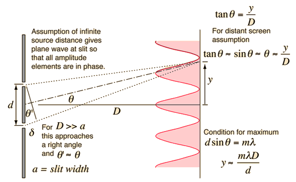
This is an image of a thin wall with two slits with some vertical distance between each other denoted by d and each slit has some width denoted by a. From the top slit there is a line that goes at some angle from the lower vertical labeled as theta prime. From the center of d is another dashed line that is at some angle theta from the horizontal that ends at the center of no light and there is a horizontal distance D to the back wall from the slits. If there was a light shined on the other side of the slit wall, there would be band of light and no light and the distance between the areas of no light are denoted by y. There are notes that says the an assumption of infinite source distance gives plane wave at the slit so that all amplitude elements are in phase. And, for when the distance between the two slits and the back wall is much greater than the width of the slit, this approaches the right angle and theta prime is approximately equal to theta. And, tangent of theta is equal to the distance between the the areas of no light divided by the horizontal distance, for distance screen assumption, this is approximately equal to sine theta which is approximately equal to theta. And, for a maximum condition, the vertical distance between the slits multiplied by sine theta is equal to m multiplied by lambda.

From a single slit diffraction to mutli slit diffraction the single slit forms an envelope where the sharpness of bright peaks become more sharp as the number of slits is increased.

This is an image of four different kinds of slit apparatuses. The first shows a single slit diffraction where there is a very intense central maximum and two faint with lower intensity fringes. The double slit shows the central maximum labeled as the single slit envelope and two slightly lower intense peaks on either side and lower intense fringes. The three slit shows the central maximum labeled as the single slit envelope and two slightly lower intense peaks on either side and even slightly lower intense peaks on either side of those with less intense fringes. The five slit shows the central maximum labeled as the single slit envelope and two slightly lower intense peaks on either side with more fringes on either side. This is to show that with increasing slits, the greater the sharpening of the fringes.

Mathematical

Mathematical Representation uses equation(s) to describe and analyze the situation.

A representation with the words Young’s double slit interference on the top. There is an equation that shows that the multiplication of the distance between slits and the sine of the diffraction angle of the mth order fringe which is equal to the product of the mth order fringe value and the wavelength. This is also written in words below.


A representation with the words Young’s double slit interference on the top. There is an equation that shows that the distance from the central maxima to the mth order bright fringe is approximately equal to the mth order value multiplied by the wavelength and the distance between the slits and the screen, divided by the distance between the slits. This is also written in words below.


A representation with the words single slit interference on the top. There is an equation that shows that the width of the slit multiplied by the sine of the diffraction angle of the pth order dark fringe is equal to the product of the order of the dark fringe and the wavelength. This is also written in words below.


A representation with the words single slit interference on the top. There is an equation that shows that the diffraction angle of the pth order dark fringe is approximately equal to the order of the dark fringe multiplied by the wavelength divided by the slit width. This is also written in words below.


A representation with the words single slit interference on the top. There is an equation that shows that the distance to the dark fringe from the central maxima for the pth order dark fringe is equal to the order of the dark fringe multiplied by the wavelength and distance between the slit and screen, divided by the slit width. This is also written in words below


A representation with the words single slit central maxima width on the top. There is an equation that shows that the width of the central maxima is equal to twice the wavelength multiplied by the distance between the slit and screen, divided by the slit width. This is also written in words below.

Graphical

Graphical Representation describes the situation through use of plots and graphs.


Descriptive

Descriptive Representation describes the physical phenomena with words and annotations.


Experimental

Arrow that takes you back to the Fundamentals section