BoxSand's Resources
Introduction
Superposition of Waves
When two waves enter the same region of space at the same time they interfere in a way that obeys the Superposition of Waves. This addition of waves creates places where the peaks line up and the resultant wave is larger, which would manifest as a bright spot for light waves. There are also regions where the peak from one wave is lined up with the trough from the other and the resultant is wave cancelation, where their amplitudes add to zero and there would be a dark spot. These constructive and destructive areas are seperated by an entire gradient of partially constructive and partially destructive. The resulting interference pattern is one of the defining features of a wave.
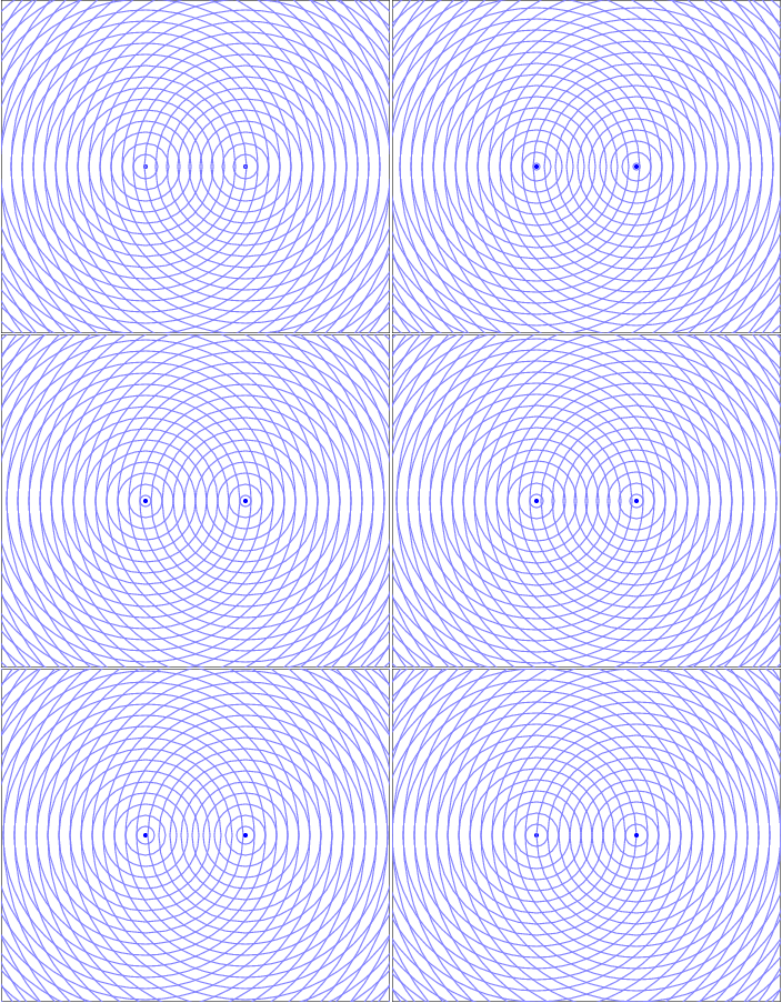
To learn more about general two source interference, visit the fundamentals of Superposition of Waves.
Wave Interpretation of Light - Young's Double Slit Interference
The theory of Electromagnetic Radiation Wave Theory is one of the most tested and confirmed theories in physics. It relies heavily on the experimental fact that light has wave-like properties. These wave-like properties are displayed by the interference effects that has only been observed in wave systems. The hallmark experiment that enabled us to observe the effect was Young's Double Slit Experiement.
To observe the interference of two sources you need two, coherent, single frequency sources. Essentially you would like two identical sources. The clever way Young achieved this was by isolating a single color of light then sending that light through two small slits. Each slit acts like a new wave source due to the diffraction of light, which is the effect that light "bends" around corners and spreads out when passing through an opening. Since each slit acts like a new source, and each originated from the same source, they are two coherent, single frequency (same color) sources. The diagram below shows a snapshot of the waves as they interfere.
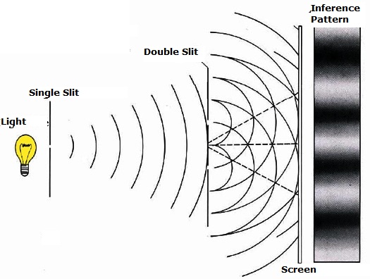
The modern technology of a LASER (Light Amplification through the Stimulation of Electromagnetic Radiation) has made this experiment much easier due to the very high intensity soures they provide. The experiment also enables one to measure the wavelength of visable light, something on the order of hundreds of nanometers, a size only an order of magnitude greater than the size of atoms. For nearly 100 years this was the only way to probe scales this size scale and it still remains as one of the best.
The geometry of Young's Double Slit is below.
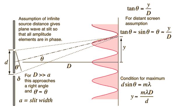
Here the dstance between the slits is $d$ and the screen observing the interference effect is a distance $D$ away from the slits. The central maximum is located along the perpendicular bisector between the two sources where the Path Length Difference (PLD) between the two sources is zero. The condition for constructive interference is for the PLD to be an interger ($m$) multiple of the wavelength. So as you move away from the central maximum and go from constructive to destructive and back to constructive, you've increased the PLD by one whole wavelength. These bright spots are called interference fringes. Using the condition for constructive interference $PLD = m \lambda$ and the geometery that $PLD=d sin(\theta)$, you arrive at the overall condition for constructive interference.
$d sin{\theta}=m \lambda$
The distance $y$ is measured from the central maximum and can be related to the angle ($\theta$) and the distance $D$ by the equation $tan (\theta) = \frac{y}{D}$. In most cases, where $\lambda << d$ the angle is so small that $sin (\theta) \approx \theta$. Since $tan (\theta) = \frac{sin(\theta)}{\cos(\theta)}$ and $\cos(\theta) \approx 1$ for very small angles, $tan(\theta) \approx sin(\theta) \approx \theta$. This allows a more simple connection between the variables shown in the equation below, but note, this only if the angles are very small.
$y \approx \frac{m \lambda D}{d}$, if $\lambda << d$
Multi-Slit Interference
A preferred experiment to measure the wavelength of light is the multi-slit experiment. Instead of only two openings, you have multiple slits, which has the effect of sharpening the constructive interference peaks. The multi-slit apparatus is called a diffraction grating when light passes through it and a reflection grating when light reflects off of it. Below is a diagram for a diffraction grating.
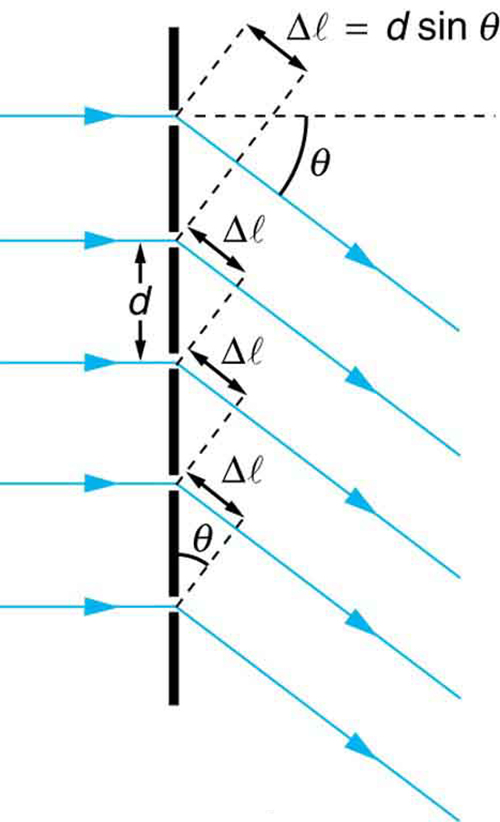
Here the first slit interferes with the second and the second with the third, and so on. Each subsequent slit has the same PLD condition as for a double slit. It is a bunch of double slits slightly shifted from each other. The result is a sharper set of interfrence fringes and the same conditions and equations as for the double slit.
Single Slit Interference
Once you have a wave picture of light and understand superposition, the inteference patterns of the double slit and muti-slit setups are not wierd. But what's truely a mind bender is when passing light through a single slit you also observe an interference pattern, although one different from the double slit. To understand this effect you must consider Huygens Principle which states that each point on a wavefront can act as a new spherical source (left figure).
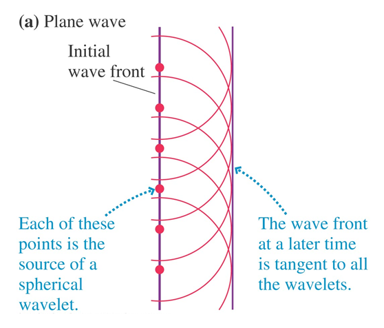
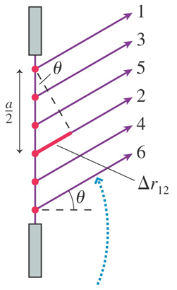
Each new spherical source interfere to create the next wavefront, which can then be a set of new spherical sources. This may seem counter intuitive and we don't know if light really behaves this way, but if modeling it this way is consistent with observation, we can't throw it out as a possibility. In fact this model then helps us understand the single slit interference pattern. Now waves generated at the top of the source can interfere with waves on the bottom of the source (figure above on the right).
The interference pattern is similar in that there are light and dark regions but it differs in the locations of the maxima and minima.
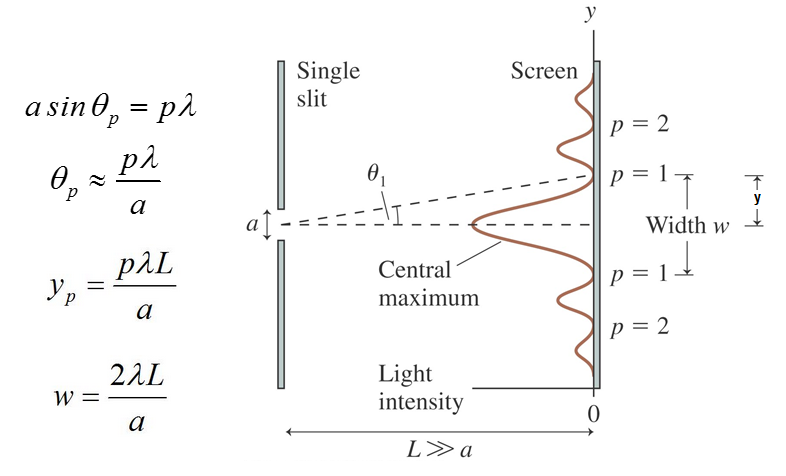
The interference is also often discribed by the locations of the destructive interference points. Here the integer $p$ is describing the order of the dark fringes. The width of the cental maximum ($w$) can be found by doubling $y_1$.
To see the difference between the single and the double slit interference patterns, along with the effects of sharpening the fringes by adding more slits, refer to the figure below.

Videos
Pre-lecture Videos: Watch these videos before doing the pre-lecture assignment, ** denotes supplemental but suggested
Review from last term **
Interference review (17min) **
Interference example - radar detection (17min) **
Interference example - radar detection (17min) Youngs Double Slit - Apparatus and conceptual (15min)
Young's Double Slit
Youngs Double Slit - Apparatus and conceptual (15min)
Youngs Double Slit - Apparatus and conceptual (15min)
Youngs Double Slit - Apparatus and conceptual review(2min) **
Youngs Double Slit - Apparatus and conceptual review(2min)
Youngs Double Slit - governing equations (6min)
Youngs Double Slit - governing equations (6min)
Youngs Double Slit - example - simple with small angle (5min) **
Youngs Double Slit - example - simple with small angle (5min)
Diffraction and Reflection Gratings
Diffraction Grating - conceptual (6min)
Diffraction Grating - conceptual (6min)
Reflection Grating - conceptual (4min)
Reflection Grating - conceptual (4min)
Reflection Grating - simple example - beetle (2min) **
Reflection Grating - simple example - beetle (2min)
Spectroscopy and Single Slit Interference
Spectroscopy - conceptual (11min) **
Spectroscopy - conceptual (11min)
X-Ray Bragg Diffraction - conceptual (7min) **
X-Ray Bragg Diffraction - conceptual (7min)
Single Slit Diffraction (11min) **
Single Slit Diffraction (11min)
Single Slit Diffraction - equations(4min)
Single Slit Diffraction - equations(4min)
Diffraction (4min)
Single Slit Diffraction - example (2min) **
Single Slit Diffraction - example (2min)
Diffraction - circular apperatures (4min) **
Diffraction - circular apperatures (4min)
Web Resources
Text
On OpenStax, these 5 short sections, Wave Aspect of Light, Hyugen's Principle, Young's Double Slit Experiment, Single Slit Diffraction, and Double Slit Diffraction contain the information for this section. This link takes you to the first section, Wave Aspect of Light.
| Wave Aspect of Light | Huygen's Principle: Diffraction | Young's Double Slit Experiment |
| Multiple Slit Diffraction | Single Slit Diffraction |
The physics classroom has two relevent sections, The Wavelike Behaviors of Light, and Two Point Source Interference.
Kathy Hadley has a great explaination of the Single Slit interference and Huygens Principle.
Hyperphysics usual reference, this time for multi-slit interference. You can get to Single slit and diffraction gratings from the links in the frist box.
This is a good, large powerpoint which covers wave interference and diffraction,
Other Resources
This link will take you to the repository of other content related resources .
Videos
Doc Schuster covers wave interference,
https://www.youtube.com/watch?v=_N5Y9PVxHLY
Doc Shuster covers single slit diffraction,
https://www.youtube.com/watch?v=ps8IBv5_VeM
Some mathematicas behind double slit diffraction,
https://www.youtube.com/watch?v=KeHry37evb4
Other Resources
This link will take you to the repository of other content related resources .
Simulations
Phet - wave interference,
For additional simulations on this subject, visit the simulations repository.
Demos
Practice
Fundamental examples
(1) A red laser with wavelength $\lambda = 700$ nm shined on a double-slit with width $d=10$ mm. The screen is located $D= 2 $ m away from the slit. How far up from the central maximum is the $m=2$ bright fringe?
(2) How does the position of the 2nd bright fringe in example 1 change if the wavelength used is $\lambda_{new} = 350$ nm instead of $\lambda_{old} = 700 $ nm?
(3) In a single-slit experiment, the width of the central maximum is $1.5 $ mm. The screen is 1 meter from the slit and the wavelength of light used in this experiment is $360 $ nm. (a) What is the size of the slit? (b) How much wider would the central maximum be if the wavelength was tripled?
(4) In a single-slit experiment, the second dark fringe is located 7.5 cm from the center of the central maximum on a screen located $L = 3 m$ away from the slit. What is the distance between the second dark fringe and the third dark fringe that is located on the other side of the central maximum? The wavelength of the illuminating light is $\lambda = 600 $ nm.
Solutions found HERE
Short foundation building questions, often used as clicker questions, can be found in the clicker questions repository for this subject.
Practice Problems
Conceptual Problems
BoxSand's multiple select problems
BoxSand's quantitative problems
Recommended example practice problems
- PhysLabs
- Double Slit Worksheet: Website Link
- Single Slit Worksheet: Website Link
- OpenStax Practice problems at the end of sections
- Young's Double Slit: Website Link
- Multiple Slit Diffraction: Website Link
- Single Slit Diffraction: Website Link
For additional practice problems and worked examples, visit the link below. If you've found example problems that you've used please help us out and submit them to the student contributed content section.